Download presentation
Presentation is loading. Please wait.

1
Outline Stokes Vectors, Jones Calculus and Mueller Calculus
Optics of Crystals: Birefringence Common polarization devices for the laboratory and for astronomical instruments Principles of Polarimetry: Modulation and Analysis. Absolute and Relative Polarimetry Principles of Polarimetry: Spatial modulation, Temporal modulation, Spectral modulation Principles of Polarimetry: Noise and errors Spurious sources of polarization

2
Stokes Vector, Jones Calculus, Mueller Calculus playing around with matrices
A. López Ariste

3
Assumptions: A plane transverse electromagnetic wave Quasi-monochromatic Propagating in a well defined direction z

4
Jones Vector

5
Jones Vector: It is actually a complex vector with 3 free parameters
It transforms under the Pauli matrices. It is a spinor

6
The Jones matrix of an optical device
In group theory: SL(2,C)
")
7
From the quantum-mechanical point of view, the wave function cannot be measured directly.
Observables are made of quadratic forms of the wave function: J is a density matrix : The coherence matrix

8
Like Jones matrices, J also belongs to the SL(2,C) group, and can be decomposed in the basis of the Pauli matrices. Is the Stokes Vector

9
The Stokes vector is the quadractic form of a spinor
The Stokes vector is the quadractic form of a spinor. It is a bi-spinor, or also a 4-vector

10
4-vectors live in a Minkowsky space with metric (+,-,-,-)
")
11
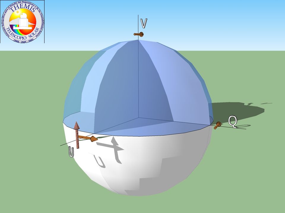
The Minkowski space I Partially polarized light Cone of
(fully polarized) light Fully polarized light V Q
 light. Fully polarized. light. V. Q.")
13
M is the Mueller matrix of the transformation

14
From group theory, the Mueller matrix belongs to a group of transformations which is the square of SL(2,C) Actually a subgroup of this general group called O+(3,1) or Lorentz group
 or Lorentz group.")
15
The cone of (fully polarized) light
Lorentz boost = de/polarizer, attenuators, dichroism V Q

16
The cone of (fully polarized) light
3-d rotation = retardance, optical rotation V Q

17
Mueller Calculus Any macroscopic optical device that transforms one input Stokes vector to an output Stokes vector can be written as a Mueller matrix Lorentz group is a group under matrix multiplication: A sequence of optical devices has as Mueller matrix the product of the individual matrices

18
Mueller Calculus: 3 basic operations
Absorption of one component Retardance of one component respect to the other Rotation of the reference system

19
Mueller Calculus: 3 basic operations
Absorption of one component

20
Mueller Calculus: 3 basic operations
Absorption of one component Retardance of one component respect to the other

22
Mueller Calculus: 3 basic operations
Absorption of one component Retardance of one component respect to the other Rotation of the reference system

24
Optics of Crystals: Birefringence
A. López Ariste

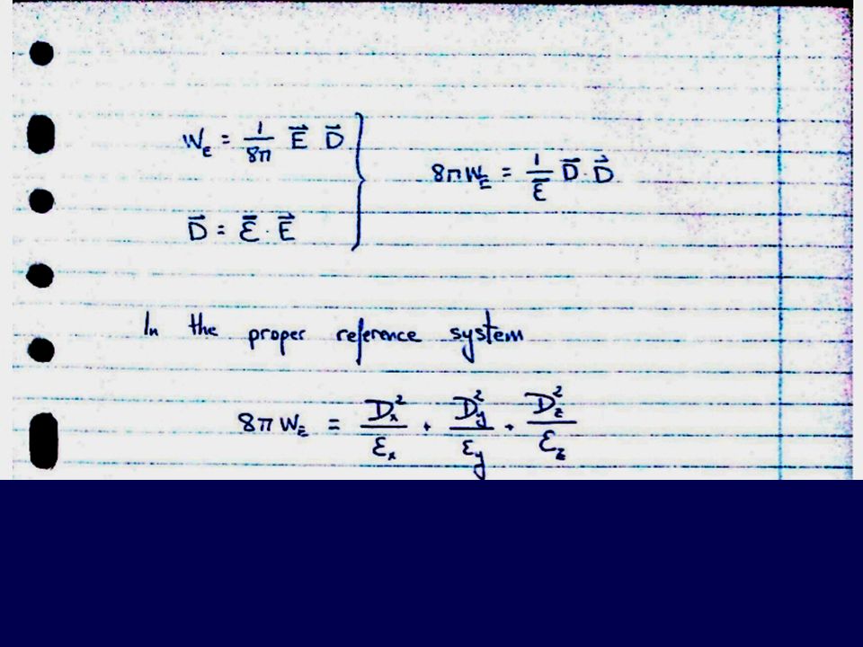
26
Chapter XIV, Born & Wolf

27
!!

31
Ellipsoïd

32
Ellipsoïd

33
Three types of crystals
A spherical wavefront

34
Three types of crystals
Two apparent waves propagating at different speeds: An ordinary wave, with a spherical wavefront propagating at ordinary speed vo An extraordinary wave with an elliptical wavefront, its speed depends on direction with characteristic values vo and ve

37
Three types of crystals

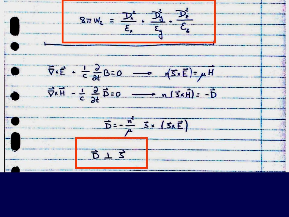
40
The ellipsoïd of D in uniaxial crystals
z s The ellipsoïd of D in uniaxial crystals De The two propagating waves are linearly polarized and orthogonal one to each other Do

42
Typical birefringences
Quartz Calcite Rutile Lithium Niobate

43
Common polarization devices for the laboratory and for astronomical instruments
A. López Ariste

44
Linear Polarizer

45
Retarder

47
Savart Plate

48
Glan-Taylor Polarizer
Glan-Taylor.jpg

49
Glan-Thompson Polarizing Beam-Splitter

50
Rochon Polarizing Beamsplitter

51
Polaroid

52
Dunn Solar Tower. New Mexico

53
Typical birefringences
Quartz Calcite Rutile Lithium Niobate Zero-order waveplates Multiple-order waveplates

54
Waveplates

56
Principles of Polarimetry Modulation Absolute and Relative Polarimetry
A. López Ariste

57
How to switch from Measure # 1 to Measure # 2?
Measure # 1 : I + Q Measure # 2 : I - Q Subtraction: 0.5 (M1 – M2 ) = Q Addition: (M1 + M2 ) = I How to switch from Measure # 1 to Measure # 2? MODULATION
 = Q. Addition: 0.5 (M1 + M2 ) = I. How to switch from Measure # 1 to Measure # 2 MODULATION.")
58
Measure # 1 : I + Q Measure # 2 : I - Q
Subtraction: 0.5 (M1 – M2 ) = Q Addition: (M1 + M2 ) = I Principle of Polarimetry Everything should be the same EXCEPT for the sign
 = Q. Addition: 0.5 (M1 + M2 ) = I. Principle of Polarimetry. Everything should be the same EXCEPT for the sign.")
59
MODULATION

60
MODULATION

61
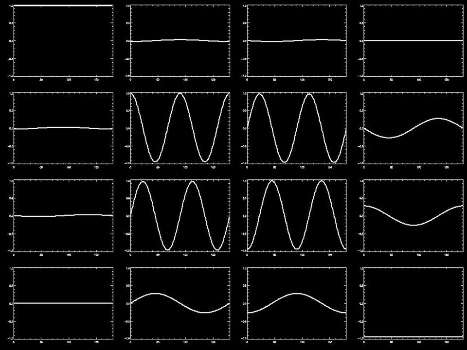
O is the Modulation Matrix

62
MODULATION Conceptually, it is the easiest thing
Is it so instrumentally? Is it efficient respect to photon collection, noise and errors?

63
MODULATION Del Toro Iniesta & Collados (2000)
Asensio Ramos & Collados (2008) MODULATION
 MODULATION.")
64
MODULATION Del Toro Iniesta & Collados (2000)
Asensio Ramos & Collados (2008) Del Toro Iniesta & Collados (2000) MODULATION
 Del Toro Iniesta & Collados (2000) MODULATION.")
65
MODULATION

66
Design of a Polarimeter
Specify an efficient modulation scheme: The answer is constrained by our instrumental choices

67
Absolute vs. Relative Polarimetry
Efficiency in Q,U and V limited by efficiency in I What limits efficiency in I?

68
Absolute vs. Relative Polarimetry
What limits efficiency in I? Measure # 1 : I + Q Measure # 2 : I - Q Subtraction: 0.5 (M1 – M2 ) = Q Addition: (M1 + M2 ) = I Principle of Polarimetry Everything should be the same EXCEPT for the sign
 = Q. Addition: 0.5 (M1 + M2 ) = I. Principle of Polarimetry. Everything should be the same EXCEPT for the sign.")
69
Absolute vs. Relative Polarimetry
What limits efficiency in I? Measure # 1 : I + Q Measure # 2 : I - Q Subtraction: 0.5 (M1 – M2 ) = Q Addition: (M1 + M2 ) = I Usual photometry of present astronomical detectors is around 10-3 Principle of Polarimetry Everything should be the same EXCEPT for the sign
 = Q. Addition: 0.5 (M1 + M2 ) = I. Usual photometry of. present astronomical detectors is around Principle of Polarimetry. Everything should be the same EXCEPT for the sign.")
70
Absolute vs. Relative Polarimetry
What limits efficiency in I? Usual photometry of present astronomical detectors is around 10-3 You cannot do polarimetry better than photometry

71
Absolute vs. Relative Polarimetry
What limits efficiency in I? Usual photometry of present astronomical detectors is around 10-3 You cannot do ABSOLUTE polarimetry better than photometry

72
Absolute vs. Relative Polarimetry
Absolute error : 10-3 I Relative error : 10-3 Q

73
Absolute vs. Relative Polarimetry
Li 6708 Absolute error : 10-3 I Relative error : 10-3 Q

75
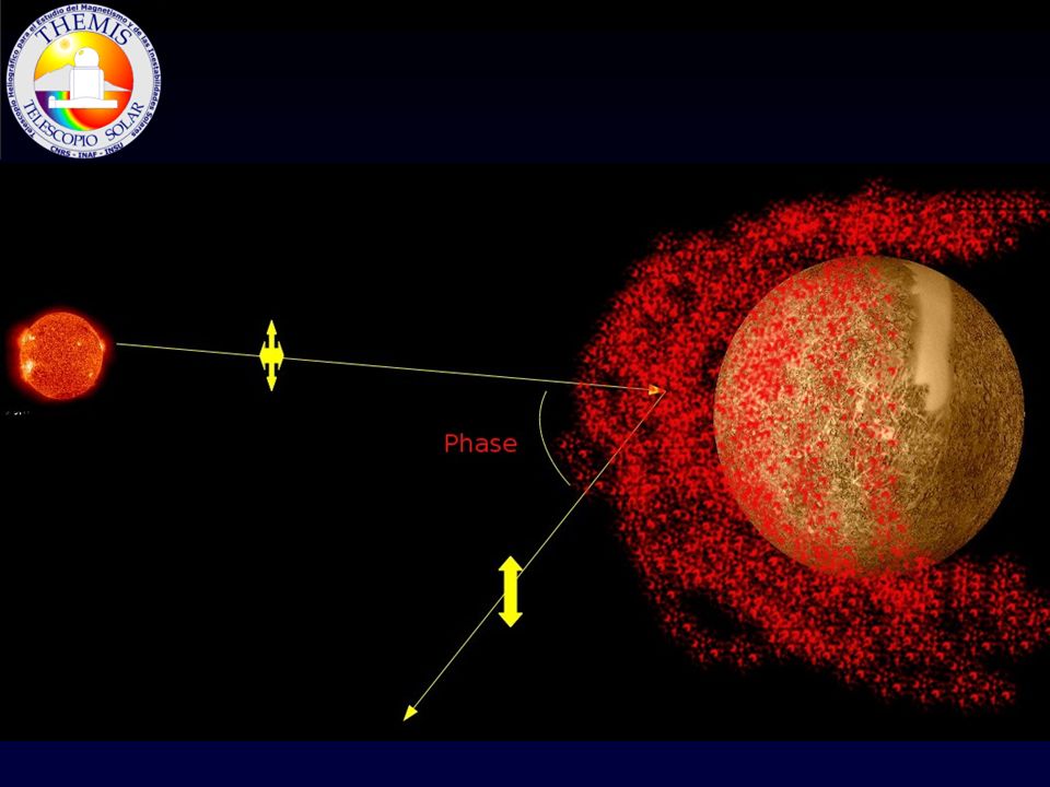
D2 D1 D2 Phase de 45 deg Phase de 102 deg

76
Design of a Polarimeter
Specify an efficient modulation scheme: The answer is constrained by our instrumental choices Define a measurement that depends on relative polarimetry, if a good sensitivity is required

77
Principles of Polarimetry Spatial modulation, Temporal modulation, Spectral modulation
A. López Ariste

78
How to switch from Measure # 1 to Measure # 2?
Measure # 1 : I + Q Measure # 2 : I - Q Subtraction: 0.5 (M1 – M2 ) = Q Addition: (M1 + M2 ) = I How to switch from Measure # 1 to Measure # 2? MODULATION
 = Q. Addition: 0.5 (M1 + M2 ) = I. How to switch from Measure # 1 to Measure # 2 MODULATION.")
79
How to switch from Measure # 1 to Measure # n?

80
Analyser: Calcite beamsplitter

81
Analyser: Rotating Polariser

82
Analyser: Calcite beamsplitter
2 beams ≡2 images Spatial modulation Analyser: Rotating Polariser 2 angles ≡ 2 exposures Temporal modulation

83
Modulator: What about U and V?

84
Modulator:

85
Modulator:

86
Modulator: Rotating λ/4

87
The basic Polarimeter Modulator Analyzer

88
Examples QW1 QW2 Measure T1 0° 0 ° Q T2 22.5 ° U T3 -45 ° V T4 45 ° -V
2 Quarter-Waves + Calcite Beamsplitter QW1 QW2 Measure T1 0° 0 ° Q T2 22.5 ° U T3 -45 ° V T4 45 ° -V ….

89
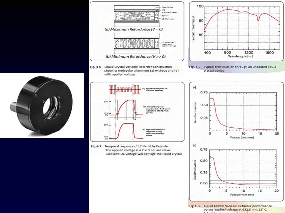
LCVR Calcite

90
Examples Rotating Quarterwave plate + Calcite Beamsplitter
Photelastic Modulators (PEM) + Linear Polariser
 + Linear Polariser.")
91
Spectral Modulation Chromatic waveplate: Followed by an analyzer

92
See Video from Frans Snik (Univ. Leiden)
Spectral Modulation Chromatic waveplate: Followed by an analyzer See Video from Frans Snik (Univ. Leiden)
")
93
Principles of Polarimetry Noise and errors
A. López Ariste

94
Sensitivity vs. Accuracy
SENSITIVITY: Smallest detectable polarization signal related to noise levels in Q/I, U/I, V/I. RELATIVE POLARIMETRY ACCURACY: The magnitude of detected polarization signal That can be quantified Parametrized by position of zero point for Q, U, V ABSOLUTE POLARIMETRY

95
Sensitivity vs. Accuracy
SENSITIVITY: Smallest detectable polarization signal related to noise levels in Q/I, U/I, V/I. RELATIVE POLARIMETRY Gaussian Noise (e.g. Photon Noise, Camera Shot Noise)
")
96
Correcting some unknown errors Spatio-temporal modulation
Goal: to make the measurements symmetric respect to unknown errors in space and time I+V Detectin in different pixels I-V Exposure 1

97
Spatio-temporal modulation
Goal: to make the measurements symmetric respect to unknown errors in space and time I+V I-V Detection at different times Detectin in different pixels I-V I+V Exposure 1 Exposure 2

98
Spatio-temporal modulation
I+V I-V I-V I+V Exposure 1 Exposure 2

99
Spatio-temporal modulation
Let’s make it more general

100
Cross-Talk Is this true? This is our polarimeter
This is what comes from the outer universe Is this true?

103
CrossTalk

105
Solutions to Crosstalk
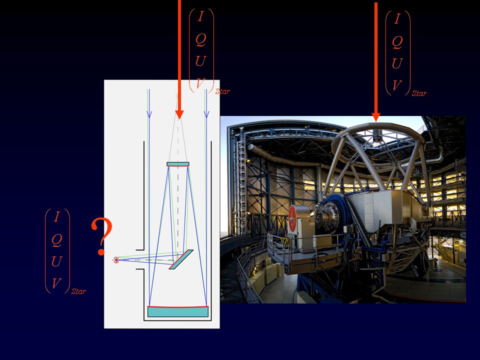
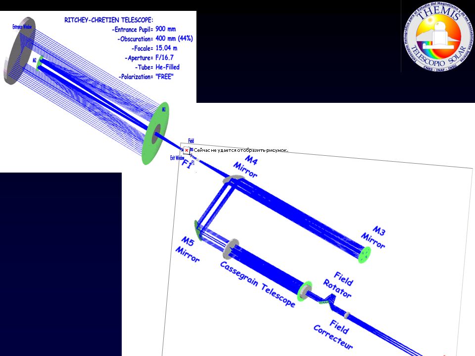
Avoid it: Measure it Mirrors with spherical symmetry (M1,M2) introduce no polarization Cassegrain-focus are good places for polarimeters THEMIS, CFHT-Espadons, AAT-Sempol,TBL-Narval,HARPS-Pol,… Given find its inverse and apply it to the measurements It may be dependent on time and wavelength It forces you to observe the full Stokes vector
 introduce no polarization. Cassegrain-focus are good places for polarimeters. THEMIS, CFHT-Espadons, AAT-Sempol,TBL-Narval,HARPS-Pol,… Given find its inverse and apply it to the measurements. It may be dependent on time and wavelength. It forces you to observe the full Stokes vector.")
106
Dunn Solar Tower. New Mexico

108
Solutions to Crosstalk
Compensate it Several procedures: Introduce elements that compensate the instrumental polarization Measure the Stokes vector that carries the information Project the Stokes vector into the Eigenvector of the matrix

Similar presentations


, Laurent Parès 2, Jean-Michel Reess 1, Pernelle Bernardi.>")


 Calcite (optically anisotropic) Calcite crystal with two polarizers at right.>")

>")


