Download presentation
Presentation is loading. Please wait.

1
Radio Receivers Al Penney VO1NO

2
Role of the Receiver The Antenna must capture the radio wave.
The desired frequency must be selected from all the EM waves captured by the antenna. The selected signal is usually very weak and must be amplified. The information carried by the radio wave, usually an audio signal, must be recovered – Demodulation. The audio signal must be amplified. The amplified audio signal must then be converted into sound waves using a speaker or headphones.

3
The 3 S’s of Receivers Sensitivity Selectivity Stability

4
Sensitivity Refers to the minimum signal level that the receiver can detect. Measured in Microvolts or fractions of Microvolts at 50 Ohm, or dbm - db below 1 mW at 50Ω, e.g dbm. Sensitivity given as “MDS” (minimum discernable signal) or 10db S/N (signal to noise ratio) or S+N/N ratio. The greater the sensitivity (ie: the smaller the number of microvolts) the weaker a signal it can receive.
 or 10db S/N (signal to noise ratio) or S+N/N ratio. The greater the sensitivity (ie: the smaller the number of microvolts) the weaker a signal it can receive.")
5
Sensitivity Very weak signals can be received – sensitivity is generally not an issue with modern receivers. Between 1.7 and 24.5 MHz on SSB, the Kenwood TS-870 has a sensitivity of 0.2 microvolts or less.

6
Selectivity Refers to the receiver’s ability to separate two closely spaced signals. The more selective a receiver, the narrower the bandwidth and/or the steeper the filter skirt.

7
Selectivity Specified as the bandwidth at 6 dB attenuation, and at 60 dB attenuation (ie: the –6 dB and –60 db points). Filter Skirt steepness is perhaps THE key characteristic that separates the boys from the men in HF receiver design! Example: On SSB the Kenwood TS-870 has a selectivity of 2.3 kHz at – 6 dB and 3.3 kHz at – 60 dB. This is a very selective receiver.

8
Ideal Receiver Selectivity

9
Actual Receiver Selectivity
Filter Skirt

10
Stability The receiver’s ability to remain on a frequency for a period of time. Unintended change in frequency is called drift. Specified as number of Hz drift over a period of time after warmup, or as ppm (part per million) for more modern radios. Not an issue for modern receivers, but is a consideration for older designs, especially those using vacuum tubes.
 for more modern radios. Not an issue for modern receivers, but is a consideration for older designs, especially those using vacuum tubes.")
11
Other Receiver Characteristics
Frequency precision: ability to determine the frequency. Resettability: ability to return to a frequency. Interference rejecting features: filters, DSP, noise blanker, noise limiter, RF preselector. Dynamic range: range of signal strength through which the receiver operates properly. The dynamic range of a radio receiver is essentially the range of signal levels over which it can operate. The low end of the range is governed by its sensitivity whilst at the high end it is governed by its overload or strong signal handling performance. Specifications generally use figures based on either the inter-modulation performance or the blocking performance.

12
Cross Modulation Cross Modulation occurs when a strong signal is too powerful for the receiver’s front end (first RF Amplifier) to pass through without distortion. It results in the wanted signal being Amplitude Modulated by the strong unwanted signal ie: the unwanted signal can be heard on top of the wanted signal.
 to pass through without distortion. It results in the wanted signal being Amplitude Modulated by the strong unwanted signal ie: the unwanted signal can be heard on top of the wanted signal.")
13
Curing Cross Modulation
To prevent cross modulation, many receivers have an Attenuator that inserts a resistive pad (circuit) between the antenna and the receiver. This weakens the strong signal enough that it no longer causes problems. If the interfering signal is out of the band altogether, then an appropriate filter between the antenna and the receiver may also help. FM receivers are immune to Cross Modulation as they are unaffected by amplitude variations on received signals.
 between the antenna and the receiver. This weakens the strong signal enough that it no longer causes problems. If the interfering signal is out of the band altogether, then an appropriate filter between the antenna and the receiver may also help. FM receivers are immune to Cross Modulation as they are unaffected by amplitude variations on received signals.")
14
Attenuator – Kenwood TS-950SDX

15
Intermodulation “Intermod” is sometimes incorrectly called Cross Modulation, but is a different phenomena. It is the result of two or more signals of different frequencies being mixed together, forming additional signals at frequencies that are not, in general, at harmonic frequencies (integer multiples) of either. The mixing usually takes place inside the receiver, but can even take place at rusty fence joints! Very prevalent problem on 2M and 70cm FM when driving through downtown!
 of either. The mixing usually takes place inside the receiver, but can even take place at rusty fence joints! Very prevalent problem on 2M and 70cm FM when driving through downtown!")
16
270 MHz 275 MHz 280 MHz 265 MHz Frequency Spectrum of intermodulation distortion in a radio-frequency signal passed through the linear broad-band amplifier I built. The process of intermodulation is due to third-order harmonics of closely spaced signals. I tested this phenomenon with two signals: a Local Oscillator (LO) at 270 MHz, +0dBm, and an RF signal at 275 MHz. (Closer spacing would push the limitations of the RF spectrum analyzer resolution). Clear intermodulation products were seen at 265 and 280 MHz. As seen on the attached graph, the intermodulation power is dB lower than the signal power. This graph nicely shows our desired signal peaks, as well as the side-band intermodulation. These closely spaced distortions would likely interfere with our signal, since it would be difficult to build a high-quality filter to cancel them out in our application. However, their overall power is more than 50 dB below the desired signal, which was sufficiently low for our purposes. We used this measurement to estimate the IP3 (third order intercept point) parameter.
 at 270 MHz, +0dBm, and an RF signal at 275 MHz. (Closer spacing would push the limitations of the RF spectrum analyzer resolution). Clear intermodulation products were seen at 265 and 280 MHz. As seen on the attached graph, the intermodulation power is dB lower than the signal power. This graph nicely shows our desired signal peaks, as well as the side-band intermodulation. These closely spaced distortions would likely interfere with our signal, since it would be difficult to build a high-quality filter to cancel them out in our application. However, their overall power is more than 50 dB below the desired signal, which was sufficiently low for our purposes. We used this measurement to estimate the IP3 (third order intercept point) parameter.")
17
Images Signals on a different frequency than the one tuned to, but which are received anyway. Occurs because of the frequency conversions that are conducted within the receiver. Image rejection is specified in dB. The image rejection specifications for the Kenwood TS-870 are 80 dB or greater.

18
Natural Noise Natural noise, called QRN, is also called Static.
It comes from objects in the galaxy that radiate RF energy, and from natural phenomena such as lightning. The presence of natural noise sets the Noise Floor for the band in question at that particular time, and appears as a steady hiss. Lightning appears as a burst of static, and can be dealt with to some degree by noise limiters.

19
Man-Made Noise Also called QRM, Man-Made Noise generally comes from sparking equipment, and also from equipment that generates RF. Some countries use HF radars that produce sharp pulses. The best solution to most man-made noise is to eliminate it at the source, as it is often close to home. Start at home, and then search the neighborhood, using a portable receiver to track down the noise. Digital Signal Processing (DSP) is of great assistance in reducing QRM.
 is of great assistance in reducing QRM.")
20
Chinese HF Radar

22
Receiver Limitations It does no good to make HF receivers any more sensitive – they are already sensitive enough to hear the natural noise floor, and cannot hear anything below that level anyway. Any component that generates gain also generates internal noise – it is unavoidable! So, while the noise floor on VHF and UHF is much lower than HF, the quality of the active device (transistor) in the front end of the receiver determines the sensitivity of the system.
 in the front end of the receiver determines the sensitivity of the system.")
23
Signals and Noise Another way to specify the sensitivity of a receiver is to express how many microvolts of signal are required to give a certain Signal to Noise Ratio (SNR). Some use the Signal + Noise to Noise Ratio, or (S+N)/N. These ratios are specified in dB.
. Some use the Signal + Noise to Noise Ratio, or (S+N)/N. These ratios are specified in dB.")
24
Can we Increase Selectivity?
While it is possible to add filters (either discrete or virtual using DSP techniques) to increase selectivity, remember that every mode has a defined bandwidth. If the selectivity is too wide, excess noise will be received. If too narrow however, the complete signal will not be received. CW filters of 250 Hz are common, but going too narrow will result in “ringing”. Human voice requires a range of 300 – 2700 Hz. Using too narrow a filter will make the voice unintelligible.
 to increase selectivity, remember that every mode has a defined bandwidth. If the selectivity is too wide, excess noise will be received. If too narrow however, the complete signal will not be received. CW filters of 250 Hz are common, but going too narrow will result in ringing . Human voice requires a range of 300 – 2700 Hz. Using too narrow a filter will make the voice unintelligible.")
25
Frequency Calibration
YOU are responsible for ensuring that you operate within the Amateur bands! Radio dials can be analog or digital. DO NOT assume that they are always correct! Older radios use Crystal Calibrators to enable you to check the accuracy of the dial. Newer, synthesized, radios use a master time base in the microprocessor to derive frequency information. If that time base is off, so will the calibration. Use WWV / WWVH to calibrate your radio.

26
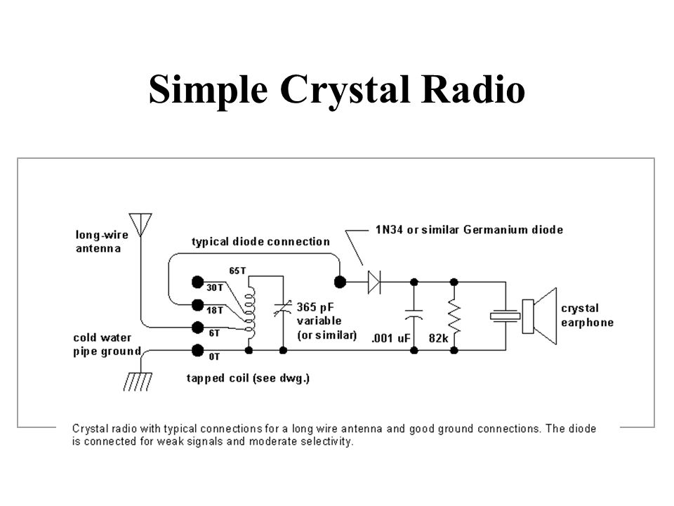
Simple Crystal Radio
27
AM Demodulation Signal Diode Action Low Pass Filter
The function of the detector is to extract the audio signal from the IF signal (a). This is carried out by a diode, which strips off the bottom half of the IF signal (b). The result is then passed through a low pass filter to remove the IF, leaving the audio intact (c). Signal Diode Action Low Pass Filter
. This is carried out by a diode, which strips off the bottom half of the IF signal (b). The result is then passed through a low pass filter to remove the IF, leaving the audio intact (c). Signal. Diode Action. Low Pass Filter.")
28
“Baby Grand” Crystal Receiver
Certainly one of the smallest radios built in the twenties, the Beaver Laboratories' Baby Grand is shown next to a quarter for size reference. This tiny crystal set dates from about 1922, or so. It is not certain if the Baby Grand was originally considered a "novelty" or a "real" crystal receiver.

29
Tuned Radio Frequency Receiver
A Tuned Radio Frequency (TRF) receiver has several RF amplifier stages followed by detector and audio amplifier stages. Each RF amplifier stage must be tuned individually. This is a very cumbersome process! For technical reasons, it is also difficult to achieve sufficient selectivity as the frequency increases.
 receiver has several RF amplifier stages followed by detector and audio amplifier stages. Each RF amplifier stage must be tuned individually. This is a very cumbersome process! For technical reasons, it is also difficult to achieve sufficient selectivity as the frequency increases.")
30
Tuned Radio Frequency Receiver
Antenna BPF BPF BPF Amp Amp Amp Det Spkr

31
American Beauty TRF Receiver
Harry Schwartzberg was president of this small company located in Kansas City, Missouri. The American Beauty is typical of the 1925 to 1926 manufacturing style of TRF receivers built by companies that weren't members of the Independent Radio Manufacturers and therefore couldn't legally build neutrodynes. The circuit uses two standard TRF amplifiers, a Detector, two stages of RC coupled Audio Amplification and one stage of transformer coupled Audio Amplification - six tubes in all. The silk-screened panels became popular in the same time period and in many other models these panels became very elaborate works of art. The American Beauty artwork features a rose in each corner to honor its namesake.

32
Regenerative Receiver
High sensitivity High selectivity (for weaker signals) Poor stability Poor immunity to overload Mediocre resettability / logging Generates a signal that can cause interference to others. Cheap + easy to build! Best performance requires careful design
 Poor stability. Poor immunity to overload. Mediocre resettability / logging. Generates a signal that can cause interference to others. Cheap + easy to build! Best performance requires careful design.")
33
Regenerative Receiver
The regenerative circuit (or self-regenerative circuit) or "autodyne" allows an electronic signal to be amplified many times by the same vacuum tube or other active component such as a field effect transistor. It consists of an amplifying vacuum tube or transistor with its output connected to its input through a feedback loop, providing positive feedback. This circuit was widely used in radio receivers, called regenerative receivers, between 1920 and World War II. The regenerative receiver was invented and patented in 1914 by American electrical engineer Edwin Armstrong when he was an undergraduate at Columbia University. Regenerative receiver circuits are still used in low-cost electronic equipment such as garage door openers. A receiver circuit that used regeneration in a more complicated way to achieve even higher amplification, the superregenerative receiver, was invented by Armstrong in 1922, but was not as widely used.
 or autodyne allows an electronic signal to be amplified many times by the same vacuum tube or other active component such as a field effect transistor. It consists of an amplifying vacuum tube or transistor with its output connected to its input through a feedback loop, providing positive feedback. This circuit was widely used in radio receivers, called regenerative receivers, between 1920 and World War II. The regenerative receiver was invented and patented in 1914 by American electrical engineer Edwin Armstrong when he was an undergraduate at Columbia University. Regenerative receiver circuits are still used in low-cost electronic equipment such as garage door openers. A receiver circuit that used regeneration in a more complicated way to achieve even higher amplification, the superregenerative receiver, was invented by Armstrong in 1922, but was not as widely used.")
34
The regenerative circuit (or self-regenerative circuit) or "autodyne" allows an electronic signal to be amplified many times by the same vacuum tube or other active component such as a field effect transistor. It consists of an amplifying vacuum tube or transistor with its output connected to its input through a feedback loop, providing positive feedback. This circuit was widely used in radio receivers, called regenerative receivers, between 1920 and World War II. The regenerative receiver was invented and patented in 1914 by American electrical engineer Edwin Armstrong when he was an undergraduate at Columbia University. Regenerative receiver circuits are still used in low-cost electronic equipment such as garage door openers. A receiver circuit that used regeneration in a more complicated way to achieve even higher amplification, the superregenerative receiver, was invented by Armstrong in 1922, but was not as widely used.

36
The Superheterodyne Receiver
In 1918 Major Edwin Armstrong developed the Superheterodyne receiver to correct the problems of the TRF radio. It mixes an incoming signal with a locally generated RF signal to produce an Intermediate Frequency (IF). That IF is then amplified, detected and turned into sound. The Superhet is still the most popular form of receiver, accounting for 99% or more!
. That IF is then amplified, detected and turned into sound. The Superhet is still the most popular form of receiver, accounting for 99% or more!")
37
Superheterodyne Receiver
Antenna Radio Frequency Amplifier Mixer Filter High Frequency Oscillator Intermediate Frequency Amplifier The signal that is picked up by the antenna passes into the receiver through an RF amplifier and enters a mixer. Another locally generated signal, produced by the HF Oscillator here but often called the Local Oscillator, is fed into the other port on the mixer and the two signals are mixed. As a result new signal are generated at the sum and difference frequencies. The output from the mixer is passed into what is termed the Intermediate Frequency or IF stages where the signal is filtered and amplified. Any of the converted signals that fall within the passband of the IF filter will be able to pass through the filter and they will also be amplified by the amplifier stages. Any signals that fall outside the passband of the filter will be rejected. The IF is then rectified by the detector stage and the resulting audio signal is amplified and turned into sound with the speaker or headphones. Tuning the receiver is simply accomplished by changing the frequency of the local oscillator. This changes the incoming signal frequency for which signals are be converted down and able to pass through the filter. Speaker Or Headphone Audio Frequency Amplifier Detector

38
Superheterodyne Receiver
Antenna Radio Frequency Amplifier Mixer Filter High Frequency Oscillator Intermediate Frequency Amplifier Speaker Or Headphone Audio Frequency Amplifier Detector

39
Antenna While technically the antenna picks up a wide range of frequencies, in practice some antennas are more narrow-banded. Resonant antennas eg: a half-wave dipole, are better able to pick up signals around their design frequency. Non-resonant antennas eg: Rhombics, can be used over a much broader frequency range.

40
Superheterodyne Receiver
Antenna Radio Frequency Amplifier Mixer Filter High Frequency Oscillator Intermediate Frequency Amplifier Speaker Or Headphone Audio Frequency Amplifier Detector

41
Radio Frequency Amplifier
The RF amplifier takes the weak signals from the antenna and amplifies them. This is usually a fairly broadband amp. In better radios it consists of a number of separate modules that cover individual bands. These modules would be selected automatically as the radio is tuned. Older radios had a manually tuned continuous preamplifier. This stage does have tuned circuits to help reject strong out-of-band signals that could cause Cross Modulation.

42
Superheterodyne Receiver
Antenna Radio Frequency Amplifier Mixer Filter High Frequency Oscillator Intermediate Frequency Amplifier Speaker Or Headphone Audio Frequency Amplifier Detector

43
HF Oscillator and Mixer
The HF Oscillator, more usually called the Local Oscillator, generates an RF signal that is higher or lower than the desired receive frequency by an amount called the Intermediate Frequency. It mixes with the signal from the RF Amp inside the Mixer. Output from the mixer is the sum and difference of the two signals. One of those two signals is the Intermediate Frequency. The choice is an engineering decision.

44
Superheterodyne Receiver
Antenna Radio Frequency Amplifier Mixer Filter High Frequency Oscillator Intermediate Frequency Amplifier Speaker Or Headphone Audio Frequency Amplifier Detector

45
Filter and IF Amplifier
The Filter can be mechanical, crystal or ceramic. Newer radios employ a synthetic filter using Digital Signal Processing (DSP) techniques. It filters out not just the non-IF signal, but is also the primary location where selectivity is obtained. The IF Amp can consist of several stages that amplifie the IF signal. Because the IF has been pre-defined by the receiver’s design, the IF amp does not need to be tuned after calibration by the manufacturer. A total of 40 – 80 dB gain.
 techniques. It filters out not just the non-IF signal, but is also the primary location where selectivity is obtained. The IF Amp can consist of several stages that amplifie the IF signal. Because the IF has been pre-defined by the receiver’s design, the IF amp does not need to be tuned after calibration by the manufacturer. A total of 40 – 80 dB gain.")
46
Receiver Filters Receivers often have several filters that can be switched in as required by the mode. Examples of the filter widths and the usual mode they would be used for are: 250 Hz CW (for severe interference) 500 Hz CW (for more relaxed conditions) 2.4 kHz SSB 6 kHz AM, possibly SSB if band is not busy
 500 Hz CW (for more relaxed conditions) 2.4 kHz SSB. 6 kHz AM, possibly SSB if band is not busy.")
48
Superheterodyne Receiver
Antenna Radio Frequency Amplifier Mixer Filter High Frequency Oscillator Intermediate Frequency Amplifier Speaker Or Headphone Audio Frequency Amplifier Detector

49
Detector Stage The amplified IF signal is sent to the Detector, where it is rectified and the RF filtered out. This leaves only a weak audio signal which is sent to the AF amplifier before going to the speaker or headphones.

50
AM Demodulation IF Transformer
An ideal diode conducts only during alternate half cycles of the input signal, and during the conducting half cycles the output current is proportional to the input voltage. An AM signal, applied to a diode detector as shown in figure 1, reproduce the modulating (audio) signal by mixing the AM sidebands with the AM carrier. It may be seen from figure 1 that the peak amplitude of each current pulse in the output is proportional to the peak amplitude of the input voltage during that particular conducting half cycle. Thus the peak, and therefore the average, values of the output current pulses follow the amplitude of the input voltage precisely during conducting half cycles and have the same waveform as the modulation envelope. Whether the output voltage would approach the peak or average value of the input voltage depends on the type of filter used in the output. If the filter is a bypass capacitor, and the internal resistance of the rectifier is small in comparison with the load resistance, then output voltage will tend to follow the peaks of the input voltage. Thus, the capacitor, CF, charges essentially to the peak input voltage during the conducting half cycles, but there is not time for appreciable discharge through the high resistance load during the non-conducting half cycles. If the bypass capacitor is too large, the time constant of the discharge will be so large that the detector output will not be able to follow the modulation envelope when the modulation envelope decreases amplitude rapidly. In addition to detection, a circuit in figure 1 has been added which is called the automatic gain control (AGC). The AGC voltage is the average value of the detector output voltage since R1 and C1 act as a filter to remove the modulating signal as well as the RF from the AGC system. This AGC voltage is therefore proportional to the amplitude of the carrier in a continuous wave system and may be used to automatically control the gain of one or more RF amplifier stages. Thus for samll input signals the RF amplifier will have high gain, but as the magnitude of the input signal increases, the gain of the RF amplifier decreases. This effect tends to keep the detector output relatively constant and prevents overdriving the RF into the saturation or cutoff regions. AGC is effectively and easily applied to a dual-gate MOSFET in the RF stage. IF Transformer
 signal by mixing the AM sidebands with the AM carrier. It may be seen from figure 1 that the peak amplitude of each current pulse in the output is proportional to the peak amplitude of the input voltage during that particular conducting half cycle. Thus the peak, and therefore the average, values of the output current pulses follow the amplitude of the input voltage precisely during conducting half cycles and have the same waveform as the modulation envelope. Whether the output voltage would approach the peak or average value of the input voltage depends on the type of filter used in the output. If the filter is a bypass capacitor, and the internal resistance of the rectifier is small in comparison with the load resistance, then output voltage will tend to follow the peaks of the input voltage. Thus, the capacitor, CF, charges essentially to the peak input voltage during the conducting half cycles, but there is not time for appreciable discharge through the high resistance load during the non-conducting half cycles. If the bypass capacitor is too large, the time constant of the discharge will be so large that the detector output will not be able to follow the modulation envelope when the modulation envelope decreases amplitude rapidly. In addition to detection, a circuit in figure 1 has been added which is called the automatic gain control (AGC). The AGC voltage is the average value of the detector output voltage since R1 and C1 act as a filter to remove the modulating signal as well as the RF from the AGC system. This AGC voltage is therefore proportional to the amplitude of the carrier in a continuous wave system and may be used to automatically control the gain of one or more RF amplifier stages. Thus for samll input signals the RF amplifier will have high gain, but as the magnitude of the input signal increases, the gain of the RF amplifier decreases. This effect tends to keep the detector output relatively constant and prevents overdriving the RF into the saturation or cutoff regions. AGC is effectively and easily applied to a dual-gate MOSFET in the RF stage. IF Transformer.")
51
Superhet Example In order to better illustrate how a Superhet receiver works, let’s look at an example of how the frequency conversion process operates. We want to receive a signal on 3.8 MHz (3800 kHz) Assume our receiver has an IF of 455 kHz.
 Assume our receiver has an IF of 455 kHz.")
52
3800 kHz signal Antenna Radio Frequency Amplifier Mixer Filter High
Oscillator Intermediate Frequency Amplifier The signal that is picked up by the antenna passes into the receiver through an RF amplifier and enters a mixer. Another locally generated signal, produced by the HF Oscillator here but often called the Local Oscillator, is fed into the other port on the mixer and the two signals are mixed. As a result new signal are generated at the sum and difference frequencies. The output from the mixer is passed into what is termed the Intermediate Frequency or IF stages where the signal is filtered and amplified. Any of the converted signals that fall within the passband of the IF filter will be able to pass through the filter and they will also be amplified by the amplifier stages. Any signals that fall outside the passband of the filter will be rejected. The IF is then rectified by the detector stage and the resulting audio signal is amplified and turned into sound with the speaker or headphones. Tuning the receiver is simply accomplished by changing the frequency of the local oscillator. This changes the incoming signal frequency for which signals are be converted down and able to pass through the filter. Speaker Or Headphone Audio Frequency Amplifier Detector

53
3800 kHz signal 3800 kHz Antenna Radio Frequency Amplifier Mixer
Filter High Frequency Oscillator Intermediate Frequency Amplifier 3800 kHz kHz = 4255 kHz The signal that is picked up by the antenna passes into the receiver through an RF amplifier and enters a mixer. Another locally generated signal, produced by the HF Oscillator here but often called the Local Oscillator, is fed into the other port on the mixer and the two signals are mixed. As a result new signal are generated at the sum and difference frequencies. The output from the mixer is passed into what is termed the Intermediate Frequency or IF stages where the signal is filtered and amplified. Any of the converted signals that fall within the passband of the IF filter will be able to pass through the filter and they will also be amplified by the amplifier stages. Any signals that fall outside the passband of the filter will be rejected. The IF is then rectified by the detector stage and the resulting audio signal is amplified and turned into sound with the speaker or headphones. Tuning the receiver is simply accomplished by changing the frequency of the local oscillator. This changes the incoming signal frequency for which signals are be converted down and able to pass through the filter. Speaker Or Headphone Audio Frequency Amplifier Detector

54
3800 kHz signal 4255 + 3800 = 8055 kHz and 4255 – 3800 = 455 kHz
Antenna Radio Frequency Amplifier Mixer Filter High Frequency Oscillator Intermediate Frequency Amplifier 3800 kHz kHz = 4255 kHz The signal that is picked up by the antenna passes into the receiver through an RF amplifier and enters a mixer. Another locally generated signal, produced by the HF Oscillator here but often called the Local Oscillator, is fed into the other port on the mixer and the two signals are mixed. As a result new signal are generated at the sum and difference frequencies. The output from the mixer is passed into what is termed the Intermediate Frequency or IF stages where the signal is filtered and amplified. Any of the converted signals that fall within the passband of the IF filter will be able to pass through the filter and they will also be amplified by the amplifier stages. Any signals that fall outside the passband of the filter will be rejected. The IF is then rectified by the detector stage and the resulting audio signal is amplified and turned into sound with the speaker or headphones. Tuning the receiver is simply accomplished by changing the frequency of the local oscillator. This changes the incoming signal frequency for which signals are be converted down and able to pass through the filter. Speaker Or Headphone Audio Frequency Amplifier Detector

55
3800 kHz signal 4255 + 3800 = 8055 kHz and 4255 – 3800 = 455 kHz
Antenna Radio Frequency Amplifier Mixer Filter 455 kHz High Frequency Oscillator Intermediate Frequency Amplifier 3800 kHz kHz = 4255 kHz The signal that is picked up by the antenna passes into the receiver through an RF amplifier and enters a mixer. Another locally generated signal, produced by the HF Oscillator here but often called the Local Oscillator, is fed into the other port on the mixer and the two signals are mixed. As a result new signal are generated at the sum and difference frequencies. The output from the mixer is passed into what is termed the Intermediate Frequency or IF stages where the signal is filtered and amplified. Any of the converted signals that fall within the passband of the IF filter will be able to pass through the filter and they will also be amplified by the amplifier stages. Any signals that fall outside the passband of the filter will be rejected. The IF is then rectified by the detector stage and the resulting audio signal is amplified and turned into sound with the speaker or headphones. Tuning the receiver is simply accomplished by changing the frequency of the local oscillator. This changes the incoming signal frequency for which signals are be converted down and able to pass through the filter. Speaker Or Headphone Audio Frequency Amplifier Detector

56
3800 kHz signal 4255 + 3800 = 8055 kHz and 4255 – 3800 = 455 kHz
Antenna Radio Frequency Amplifier Mixer Filter 455 kHz High Frequency Oscillator Intermediate Frequency Amplifier 3800 kHz kHz = 4255 kHz The signal that is picked up by the antenna passes into the receiver through an RF amplifier and enters a mixer. Another locally generated signal, produced by the HF Oscillator here but often called the Local Oscillator, is fed into the other port on the mixer and the two signals are mixed. As a result new signal are generated at the sum and difference frequencies. The output from the mixer is passed into what is termed the Intermediate Frequency or IF stages where the signal is filtered and amplified. Any of the converted signals that fall within the passband of the IF filter will be able to pass through the filter and they will also be amplified by the amplifier stages. Any signals that fall outside the passband of the filter will be rejected. The IF is then rectified by the detector stage and the resulting audio signal is amplified and turned into sound with the speaker or headphones. Tuning the receiver is simply accomplished by changing the frequency of the local oscillator. This changes the incoming signal frequency for which signals are be converted down and able to pass through the filter. 455 kHz Speaker Or Headphone Audio Frequency Amplifier Detector

57
3800 kHz signal 4255 + 3800 = 8055 kHz and 4255 – 3800 = 455 kHz
Antenna Radio Frequency Amplifier Mixer Filter 455 kHz High Frequency Oscillator Intermediate Frequency Amplifier 3800 kHz kHz = 4255 kHz The signal that is picked up by the antenna passes into the receiver through an RF amplifier and enters a mixer. Another locally generated signal, produced by the HF Oscillator here but often called the Local Oscillator, is fed into the other port on the mixer and the two signals are mixed. As a result new signal are generated at the sum and difference frequencies. The output from the mixer is passed into what is termed the Intermediate Frequency or IF stages where the signal is filtered and amplified. Any of the converted signals that fall within the passband of the IF filter will be able to pass through the filter and they will also be amplified by the amplifier stages. Any signals that fall outside the passband of the filter will be rejected. The IF is then rectified by the detector stage and the resulting audio signal is amplified and turned into sound with the speaker or headphones. Tuning the receiver is simply accomplished by changing the frequency of the local oscillator. This changes the incoming signal frequency for which signals are be converted down and able to pass through the filter. 455 kHz Speaker Or Headphone Audio Frequency Amplifier Detector AF AF AF

58
Advantages of the Superhet
Much more sensitive, selective and stable than TRF radios. By converting higher frequencies to the IF, we are able to design much more selective and sensitive filters and amplifiers that use more reliable components. Much easier to use.

59
Primary Disadvantage Superhets have one big problem however – they are subject to receiving images, or stations that are not actually on the frequency we are listening to. This occurs when a station is transmitting on a frequency twice the IF away from the desired frequency.

61
No Image 3800 kHz 4255 + 3800 = 8055 kHz and 4255 – 3800 = 455 kHz
Radio Frequency Amplifier Mixer Filter 3800 kHz 4255 kHz 455 kHz High Frequency Oscillator 3800 kHz kHz = 4255 kHz

62
Image 3800 + (2 x 455) = 4710 kHz 4255 + 3800 = 8055 kHz and
Radio Frequency Amplifier Mixer Filter 3800 kHz 4710 kHz 4255 kHz 455 kHz High Frequency Oscillator 3800 kHz kHz = 4255 kHz

63
The Solution! More expensive superhets employ double or triple conversion to improve image rejection. The first IF is chosen so that it is larger than the bandwidth of the bandpass filters in the front end of the receiver, and so the image not make it to mixer stage. The first IF signal is then amplified, and converted again to a lower IF to take advantage of the greater selectivity available at lower Intermediate Frequencies. Images: a problem with the superhet RX • If intermediate frequency (IF) is 455 kHz: • On 10m, tuned to MHz, LO is at , for 455 kHz IF • But, signal at also gives 455 kHz IF ! (image) • : : 4% difference in frequency • On 80m : MHz real : image 24% difference in frequency • Images: a problem at higher HF frequencies, if only 1 or no RF amp!
 is 455 kHz: • On 10m, tuned to MHz, LO is at , for 455. kHz IF. • But, signal at also gives 455 kHz IF ! (image) • : : 4% difference in frequency. • On 80m : MHz real : image 24% difference in. frequency. • Images: a problem at higher HF frequencies, if only 1 or. no RF amp!")
64
Advantages of a High First IF
Front End RF Amplifier’s Response Local Oscillator signal (low IF) Image Signal Desired Signal The choice of Intermediate Frequency There are two conflicts with the choice of the IF Frequency: A low intermediate frequency brings the advantage of higher stage gain and higher selectivity using high-Q tuned circuits. Sharp pass-bands are possible for narrow-band working for CW and SSB reception. A high intermediate frequency brings the advantage of a lower image response. 2 x IF (low)
 Image Signal. Desired Signal. The choice of Intermediate Frequency. There are two conflicts with the choice of the IF Frequency: A low intermediate frequency brings the advantage of higher stage gain and higher selectivity using high-Q tuned circuits. Sharp pass-bands are possible for narrow-band working for CW and SSB reception. A high intermediate frequency brings the advantage of a lower image response. 2 x IF (low)")
65
Advantages of a High First IF
Front End RF Amplifier’s Response Local Oscillator signal (low IF) Local Oscillator signal (high IF) Image Signal Image Signal Desired Signal The choice of Intermediate Frequency There are two conflicts with the choice of the IF Frequency: A low intermediate frequency brings the advantage of higher stage gain and higher selectivity using high-Q tuned circuits. Sharp pass-bands are possible for narrow-band working for CW and SSB reception. A high intermediate frequency brings the advantage of a lower image response. 2 x IF (low) 2 x IF (high)
 Local Oscillator signal. (high IF) Image Signal. Image Signal. Desired Signal. The choice of Intermediate Frequency. There are two conflicts with the choice of the IF Frequency: A low intermediate frequency brings the advantage of higher stage gain and higher selectivity using high-Q tuned circuits. Sharp pass-bands are possible for narrow-band working for CW and SSB reception. A high intermediate frequency brings the advantage of a lower image response. 2 x IF (low) 2 x IF (high)")
66
Single versus Dual Conversion Superhet Receiver

67
FM Receiver The FM receiver is very similar to an AM receiver up to the IF Amplifier. Instead of a Detector however, the FM receiver uses two different stages: Limiter Frequency Discriminator

68
FM Receiver Antenna Radio Frequency Amplifier Mixer Filter High
Oscillator Intermediate Frequency Amplifier Speaker Or Headphone Audio Frequency Amplifier Frequency Discriminator Limiter

69
Limiter The Limiter Stages are high gain amplifiers that remove all traces of Amplitude Modulation from the received signal. Static crashes are mostly amplitude modulated, and so are removed by the Limiter. This gives FM its greatest benefit – a very high SNR – Signal to Noise Ratio.

71
Frequency Discriminator
The Frequency Discriminator converts frequency variations into voltage variations. This is fed to the Audio Frequency Amplifier and then the speaker or headphones.

72
Frequency Discriminator
Common types include : Foster-Seeley Detector Ratio Detector Quadrature Detector Slope detector Phase-locked Loop This discriminator simply works on the principal that with no modulation applied to the carrier there is no ouput at the detector. Briefly T1 converts the f.m. signal to a.m. and when rectified the output is still zero because they would be equal but opposite in polarity, if modulation is applied then there is a shift in the phase of the input component with a corresponding difference in the signals out of the diodes. The difference between these outputs is the audio. As an aside, this is somewhat similar to some Automatic Fine Tuning (A.F.T.) schemes in some a.m. receivers, notably early T.V. receivers. With no frequency variation there is no output, with frequency drift there will be an output difference (in either direction) which is amplified and applied to front end tuning diodes for correction. The Foster-Seeley discriminator is a widely used FM detector. The detector consists of a special center-tapped transformer feeding two diodes in a full wave DC rectifier circuit. When the input transformer is tuned to the signal frequency, the output of the discriminator is zero. When there is no deviation of the carrier, both halves of the center tapped transformer are balanced. As the FM signal swings in frequency above and below the carrier frequency, the balance between the two halves of the center-tapped secondary is destroyed and there is an output voltage proportional to the frequency deviation. The ratio detector is a variant of the Foster-Seeley discriminator, but one diode conducts in an opposite direction. The output in this case is taken between the sum of the diode voltages and the center tap. The output across the diodes is connected to a large value capacitor, which eliminates AM noise in the ratio detector output. While distinct from the Foster-Seeley discriminator, the ratio detector will similarly not respond to AM signals, however the output is only 50% of the output of a discriminator for the same input signal. The phase-locked loop detector requires no frequency-selective LC network to accomplish demodulation. In this system, a voltage controlled oscillator (VCO) is phase locked by a feedback loop, which forces the VCO to follow the frequency variations of the incoming FM signal. The low-frequency error voltage that forces the VCO's frequency to track the frequency of the modulated FM signal is the demodulated audio output. Foster-Seeley Detector
 schemes in some a.m. receivers, notably early T.V. receivers. With no frequency variation there is no output, with frequency drift there will be an output difference (in either direction) which is amplified and applied to front end tuning diodes for correction. The Foster-Seeley discriminator is a widely used FM detector. The detector consists of a special center-tapped transformer feeding two diodes in a full wave DC rectifier circuit. When the input transformer is tuned to the signal frequency, the output of the discriminator is zero. When there is no deviation of the carrier, both halves of the center tapped transformer are balanced. As the FM signal swings in frequency above and below the carrier frequency, the balance between the two halves of the center-tapped secondary is destroyed and there is an output voltage proportional to the frequency deviation. The ratio detector is a variant of the Foster-Seeley discriminator, but one diode conducts in an opposite direction. The output in this case is taken between the sum of the diode voltages and the center tap. The output across the diodes is connected to a large value capacitor, which eliminates AM noise in the ratio detector output. While distinct from the Foster-Seeley discriminator, the ratio detector will similarly not respond to AM signals, however the output is only 50% of the output of a discriminator for the same input signal. The phase-locked loop detector requires no frequency-selective LC network to accomplish demodulation. In this system, a voltage controlled oscillator (VCO) is phase locked by a feedback loop, which forces the VCO to follow the frequency variations of the incoming FM signal. The low-frequency error voltage that forces the VCO s frequency to track the frequency of the modulated FM signal is the demodulated audio output. Foster-Seeley Detector.")
73
Receiving SSB and CW The SSB/CW receiver is very similar to an AM receiver up to the IF Amplifier. Instead of a Detector however, the SSB/CW receiver uses two different stages: Product Detector Beat Frequency Oscillator (BFO).
.")
74
Carrier is suppressed Amplitude Modulation Double Sideband Suppressed Carrier

75
Lower Sideband Upper Sideband Single Sideband Suppressed Carrier

76
SSB / CW Superheterodyne Receiver
Antenna Radio Frequency Amplifier Mixer Filter High Frequency Oscillator Intermediate Frequency Amplifier Speaker Or Headphone Audio Frequency Amplifier Product Detector Beat Freq Oscillator

77
Product Detector Because the carrier has been removed from an SSB transmission, it must be re-inserted so that the original audio can be recovered. This is accomplished using the Product Detector. The source of the carrier is the Beat Frequency Oscillator (BFO). A product detector is a type of demodulator used for AM and SSB signals, where the original carrier signal is removed. Rather than converting the envelope of the signal into the decoded waveform like an envelope detector, the product detector takes the product of the modulated signal and a local oscillator, hence the name. At least partially, it mixes the signal with the output of the local oscillator. This can be accomplished by heterodyning. The received signal is mixed, in some type of nonlinear device, with a signal from the local oscillator, to produce an intermediate frequency, referred to as the beat frequency, from which the modulating signal is detected and recovered.
. A product detector is a type of demodulator used for AM and SSB signals, where the original carrier signal is removed. Rather than converting the envelope of the signal into the decoded waveform like an envelope detector, the product detector takes the product of the modulated signal and a local oscillator, hence the name. At least partially, it mixes the signal with the output of the local oscillator. This can be accomplished by heterodyning. The received signal is mixed, in some type of nonlinear device, with a signal from the local oscillator, to produce an intermediate frequency, referred to as the beat frequency, from which the modulating signal is detected and recovered.")
78
Beat Frequency Oscillator (BFO)
The BFO is an oscillator that replaces the carrier in an SSB transmission. CW transmissions also require a carrier to “beat” against (mix with) to produce an audio tone. Older receivers use a BFO that could be varied in frequency as the operating mode is changed from USB to LSB to CW. Modern radios automatically switch the operating frequency of the BFO as the mode is changed.
 to produce an audio tone. Older receivers use a BFO that could be varied in frequency as the operating mode is changed from USB to LSB to CW. Modern radios automatically switch the operating frequency of the BFO as the mode is changed.")
79
Product Detector A product detector is a mixer used to down convert an input signal to baseband. The term, product detector, is normally used when referring to single sideband (SSB), or double sideband (DSB) demodulation, or continuous wave (CW). Essentially, it is a detector whose output is approximately equal to the product of the beat-frequency oscillator (BFO) and the RF signals applied to it. Output from the product detector is at audio frequency. Some RF filtering may be necessart at the detector output to prevent unwanted IF or BFO voltage from reaching the audio amplifier which follows the detector. In figure 2, a product detector is used to demodulate a SSB signal. The lowpass filter that follows the mixer passes only the down conversion, or difference, frequency band. Since the SSB, or DSB, signal is transmitted with no carrier, or with a supressed carrier, the frequency of the re-injected carrier in figure 2 will not be exactly the same as that of the carrier that was suppressed in the generation of the SSB, or DSB, signal. If the frequency of the re-injected carrier is not sufficiently close, then the output audio will appear to have a "Donald Duck" quality as a result of all the demodulated frequencies being in error by a constant offset.
, or double sideband (DSB) demodulation, or continuous wave (CW). Essentially, it is a detector whose output is approximately equal to the product of the beat-frequency oscillator (BFO) and the RF signals applied to it. Output from the product detector is at audio frequency. Some RF filtering may be necessart at the detector output to prevent unwanted IF or BFO voltage from reaching the audio amplifier which follows the detector. In figure 2, a product detector is used to demodulate a SSB signal. The lowpass filter that follows the mixer passes only the down conversion, or difference, frequency band. Since the SSB, or DSB, signal is transmitted with no carrier, or with a supressed carrier, the frequency of the re-injected carrier in figure 2 will not be exactly the same as that of the carrier that was suppressed in the generation of the SSB, or DSB, signal. If the frequency of the re-injected carrier is not sufficiently close, then the output audio will appear to have a Donald Duck quality as a result of all the demodulated frequencies being in error by a constant offset.")
80
Beat Frequency Oscillator

81
Audio Filters Hams sometimes employed active or passive external audio filters with older receivers in an effort to remove interference and improve selectivity. A Notch Filter can be used to remove an interfering carrier signal (ie: CW signal). To improve CW selectivity, an audio bandpass filter for 750 – 850 Hz would be appropriate. Modern radios incorporate DSP techniques even more effectively, at the IF stages rather than the audio stages.
. To improve CW selectivity, an audio bandpass filter for 750 – 850 Hz would be appropriate. Modern radios incorporate DSP techniques even more effectively, at the IF stages rather than the audio stages.")
82
MFJ- 784B DSP Filter

83
Signal Strength Meters
An S-Meter enables you to make comparisons between received signals. Unfortunately, even on identical receivers, most S-meters are not properly calibrated and will give different readings when using the same antenna. The scale is divided into 9 increments, designated S0 to S9, up to the center point of the meter. The scale is then graduated in dB, usually in multiples of 10. A signal strength report would be “S6” or “S9 plus 15 dB”.

84
S-Meter Standards According to the standards adopted by the International Amateur Radio Union (IARU) in 1981, S9 corresponds to a signal strength of 50 microvolts at the receiver’s 50 ohm impedance antenna input. Each S unit then reflects a 6dB change in signal strength. This is rarely achieved, as S-meters are often not linear in their response. Still, they give a relative indication of signal strengths!
 in 1981, S9 corresponds to a signal strength of 50 microvolts at the receiver’s 50 ohm impedance antenna input. Each S unit then reflects a 6dB change in signal strength. This is rarely achieved, as S-meters are often not linear in their response. Still, they give a relative indication of signal strengths!")
85
S-Meter

86
Software Defined Radios
Software-defined radio (SDR) is a radio communication system where components that have been typically implemented in hardware (e.g. mixers, filters, amplifiers, modulators/demodulators, detectors, etc.) are instead implemented by means of software on a personal computer or embedded system. While the concept of SDR is not new, the rapidly evolving capabilities of digital electronics render practical many processes which used to be only theoretically possible. A basic SDR system may consist of a personal computer equipped with a sound card, or other analog-to-digital converter, preceded by some form of RF front end. Significant amounts of signal processing are handed over to the general-purpose processor, rather than being done in special-purpose hardware. Such a design produces a radio which can receive and transmit widely different radio protocols (sometimes referred to as waveforms) based solely on the software used.
 is a radio communication system where components that have been typically implemented in hardware (e.g. mixers, filters, amplifiers, modulators/demodulators, detectors, etc.) are instead implemented by means of software on a personal computer or embedded system. While the concept of SDR is not new, the rapidly evolving capabilities of digital electronics render practical many processes which used to be only theoretically possible. A basic SDR system may consist of a personal computer equipped with a sound card, or other analog-to-digital converter, preceded by some form of RF front end. Significant amounts of signal processing are handed over to the general-purpose processor, rather than being done in special-purpose hardware. Such a design produces a radio which can receive and transmit widely different radio protocols (sometimes referred to as waveforms) based solely on the software used.")
88
Questions?

89
Two Section Tuning Capacitor

Similar presentations


 Receiver Demodulation Chelmsford Amateur.>")
 Transmitters>")
 ANGLE MODULATION>")


 ©2003 Glencoe/McGraw-Hill Charles A. Schuler.>")


 AMPLITUDE MODULATION>")
