Download presentation
Presentation is loading. Please wait.

1
Clutch Basics manual adjust / lube ZF Sachs Twin Extend operation & maintenance
Western Region Art Herrnberger

2
ON LINE TRAINING

3
Manual adjust clutch

4
CLUTCH OPERATION BASICS
Disconnects / Connects engine from / to transmission 99% of clutch wear occurs at vehicle start. (starting vehicle in low gear = max clutch life) Double clutching = disconnects mass of engine from trans while shifting gears.
 Double clutching = disconnects mass of engine from trans while shifting gears.")
5
Clutch Components

6
Clutch Brake Should be called the “Input Shaft” Brake

7
DISENGAGING AND

8
Diaphragm Spring generates Clamping Force of Clutch
Diaphragm pushes on Retainer, Retainer pushes on Levers, Levers push on Pressure Plate Lever ratio amplifies Diaphragm Force

9
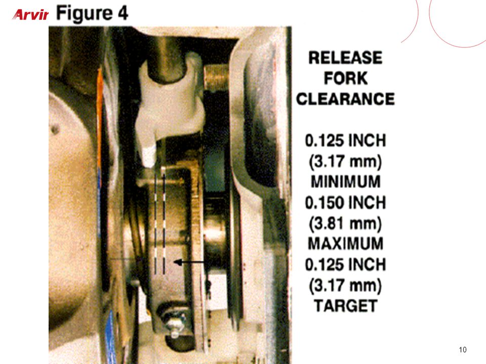
Release fork clearance
Be sure the linkage / peddle full return

11
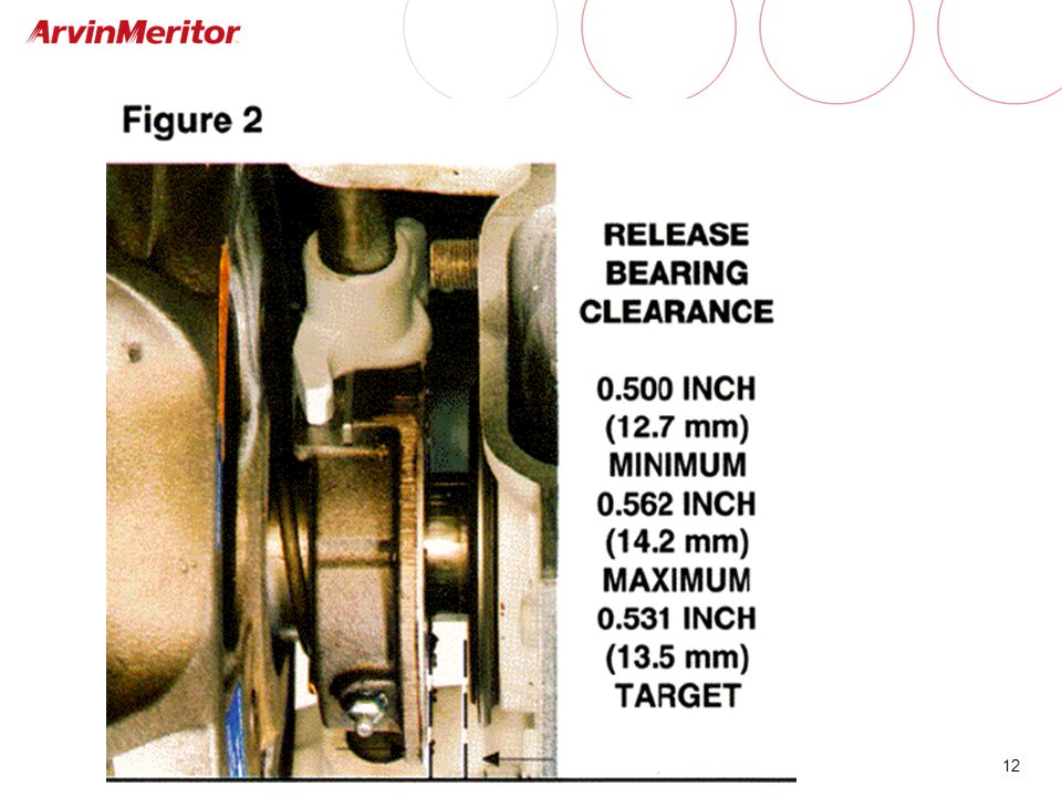
Release bearing to clutch brake clearance
Release bearing to clutch brake clearance inch /16th inch - ½ inch min

13
Is release fork to brg clearance less than 1/8 inch?
CHECK FORK CLEARANCE AT EACH SERVICE, TAKE A TURN ON THE ADJUSTING RING…. MAINTAIN 1/8 INCH = MAX CLUTCH LIFE RECORD before & after adj measurements = MAX CLUTCH LIFE

14
WHAT IS CLUTCH ADJUSTMENT?
Maintaining clamp force

15
Diaphragm Spring generates Clamping Force of Clutch
Diaphragm pushes on Retainer, Retainer pushes on Levers, Levers push on Pressure Plate Lever ratio amplifies Diaphragm Force

16
(Contact point of Diaphragm on Cover Housing is a fixed position)
Diaphragm Force (Compression) Controlled By Position of Retainer (Contact point of Diaphragm on Cover Housing is a fixed position)
 Controlled By Position of Retainer. (Contact point of Diaphragm on Cover Housing is a fixed position)")
17
Retainer Position is Controlled by Adjusting Ring
Retainer is positioned by Lever Lever orientation is a consequence of: Disc + IP/PP thickness (uncontrollable) Adjusting Ring setting (controllable) Indirectly, Adjusting Ring setting Controls Diaphragm Force
 Adjusting Ring setting (controllable) Indirectly, Adjusting Ring setting Controls Diaphragm Force.")
18
How to Properly Control Diaphragm Force, When You Can’t See inside the Clutch to Position Retainer?
(0.530”) (1/8”) Freeplay Sleeve Length is Known, Therefore Release Bearing Clearance to Clutch Brake and Freeplay is Used to Detect Retainer Position Freeplay Loss Indicates Retainer Position is Changing (Eventually Requiring Clutch Adjustment)
 (1/8 ) Freeplay. Sleeve Length is Known, Therefore Release Bearing Clearance to Clutch Brake and Freeplay is Used to Detect Retainer Position. Freeplay Loss Indicates Retainer Position is Changing (Eventually Requiring Clutch Adjustment)")
19
Diaphragm Spring Characteristic
Force Compression Stroke Dual Trace Caused By Friction (Hysteresis) Return Stroke Diaphragm Force in Frictionless System Free State Deflection
 Return Stroke. Diaphragm Force in Frictionless System. Free State. Deflection.")
20
Clutch Characteristic – Clamp Load Curve
Loss of Free-play Indicates Adjustment is Required Set Point Prior to Adjustment Set Point at Initial Installation Required Clamp Load Clutch bolted to the flywheel .530 clearance bearing to clutch brake Free state Amount of Wear Which Causes Free Play to Become Zero Free Play = Zero Bearing at .530”

21
Clutch adjustment is turning the adj ring to move the pressure plate forward to compensate for friction disc wear (Measured by position of release bearing) The following are also methods of adjusting a clutch Clutch adjustment is turning the adjusting ring Not changing height of peddle. Not taking slack out of linkage. Not extending a linkage rod, or reducing. If a turn is not made on the adjusting ring, it is not a clutch adjustment! . The pressure plate load is controlled by the position of the levers to the spring and back of pressure plate. It is maintained by adjusting ring movement. All other changes to the system are not a clutch adjustment.

22
Clutch brake clearance factors
Clutch brake wear Transmission bearing retainer wear

23
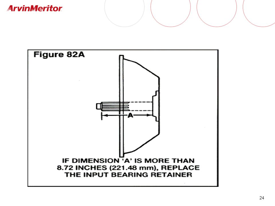
What is condition?

25
Trans input bearing retainer

26
Release Fork Does it pull straight back on Release bearing?
Wear patterns tell a story Bushings Shafts Conditions Anti rotation surfaces. Hardened forked needed?

27
Lube interval = 15,000 miles CHASSIS GREASE IN A RELEASE BEARING?
Chassis grease will not stay put at high temp

28
CLEAN OLD GREASE FROM ZERK.

29
Cross shafts & linkage

30
Block or “Cage” clutch at removal
Pressure Plate (3 inch ½ inch thick blocks at removal….keeps levers loaded)
")
31
Clutch basics Summary Maintain 1/8 fork clearance = max life
Clutch brake squeeze is 1/2 inch - 9/16th inch Make a clutch internal clutch adjustment at each service Use proper lube Do not lube the clutch brake friction surface Block / or “cage” clutch at removal

32
TWIN EXTEND clutch 15 ½ inch two plate Controlled center plate
Self adjusting Locking adjusting mechanism Open architecture clears the mechanism of dirt

33
Key Features Open architecture “free flow” design – adjustment mechanism is not confined to a narrowly clearanced packaging space. If / when dirt ingestion occurs, build–up remains in areas that do not reach adjustment mechanism

34
Key Features Patented “Controlled Center Plate” mechanism ensures full release of Both Disc Assemblies XTend locking mechanism prevents misadjustment due to system vibrations or shock loads

35
Shipping (caging ) bolts
Four 7/16 X 1.5 inch bolts

36
Initial check. Set up. 1) VIDEO 2) PDF file
 VIDEO 2) PDF file")
37
Twin Extend Self adjusting. Routine adjustment not needed
Not maintenance free, check the system at PM Normal lube interval Cage bolts must be in place to install / remove A punch and a hammer will not torque the spanner nuts

38
ZF Sachs Twin Extend clutch basics manual adjust / lube
Questions? Thank you Western Region Art Herrnberger

Similar presentations


 Service>")

 was introduced in 2011. Parts do not.>")

