Download presentation
Presentation is loading. Please wait.

1
Workshop 2012 Serge Calippe - European Technical Support HW
RapidArc® Workshop 2012 January 27-28th 2012, Aarhus, Denmark

2
Session 1a RapidArc® – Basics Technical description of RapidArc® delivery on Clinac RapidArc® delivery of the TrueBeam® accelerator Discussion Session 1b Optimize RapidArc® delivery – Technical aspect Why a specific Machine QC ? Hardware and software adjustments (MLC – Gantry – Beam performance) PMI / Machine QC (Tests, dynalog files)
 PMI / Machine QC (Tests, dynalog files)")
3
Technical description of RapidArc® delivery on Clinac
Session 1a RapidArc® – Basics Technical description of RapidArc® delivery on Clinac RapidArc® delivery of the TrueBeam® accelerator compared to Clinac)
")
4
RapidArc® – Basics

5
RapidArc® – Basics RapidArc® is a sophisticated treatment technique (….which started in Denmark in 2008) RapidArc® is a volumetric arc therapy that delivers a precisely sculpted 3D dose distribution with a single 360-degree rotation of the Linac Substantially decreases the treatment time

6
RapidArc® – Basics Modulation of the dose distribution
Varying doses per degree and dynamic MLC (DMLC) The variable dose per degree is achieved by changing both the dose rate or gantry speed MLC leaves are allowed to travel in and out + leaf Interdigitation capabilities The arc optimization algorithm, PRO (Progressive Resolution Optimizer), ensures the treatment precision. It optimizes leaf position, dose rate and gantry speed Demo..\RapidArc_Treatment_Timing.mp4
 The variable dose per degree is achieved by changing both the dose rate or gantry speed. MLC leaves are allowed to travel in and out + leaf Interdigitation capabilities. The arc optimization algorithm, PRO (Progressive Resolution Optimizer), ensures the treatment precision. It optimizes leaf position, dose rate and gantry speed. Demo..\RapidArc_Treatment_Timing.mp4.")
7
Technical description of RapidArc® delivery on Clinac

8
Technical description RapidArc® on Clinac
Operation and Control Functioning of the Clinac control system during RapidArc® delivery Synchronization of MLC, gantry and dose rate Constraints

9
Technical description RapidArc® on Clinac
A full arc is divided in simple segments defined by control points. Parameters to control? Gantry angle Dose delivered / dose rate MLC leaves positions Each control point specifies the gantry angle, cumulative fractional MU and MLC positions

10
Technical description RapidArc® on Clinac
Maximum 177 control points (at 5th level of Progressive Resolution Optimizer -PRO) 1 segment every # 2 degrees for a full turn. For each single segment: Dose rate is constant Gantry speed is constant Starting and ending of MLC leaves are known Gantry, MLC and MUs are monitored every 50ms Dose rate or gantry speed are adjusted if needed
 1 segment every # 2 degrees for a full turn. For each single segment: Dose rate is constant. Gantry speed is constant. Starting and ending of MLC leaves are known. Gantry, MLC and MUs are monitored every 50ms. Dose rate or gantry speed are adjusted if needed.")
11
RapidArc® – control points listing in Eclipse
Cumulative MU Gantry Position Dose Rate Gantry Speed An example of the RapidArc prescription as calculated and displayed by Eclipse. Each row represents control point. Note that the Dose Rate is kept at maximum whenever possible while gantry speed is varied. (see Index 59-68) Once the gantry maximum speed is reached (and that is a priority for the algorithm), the MU/degree variation is achieved by variations of the instantaneous dose rate. (see Index 69-79). The maximum gantry speed was limited in the algorithm to degrees/sec for this exapmle.
 Once the gantry maximum speed is reached (and that is a priority for the algorithm), the MU/degree variation is achieved by variations of the instantaneous dose rate. (see Index 69-79). The maximum gantry speed was limited in the algorithm to degrees/sec for this exapmle.")
12
Dicom RTplan Abstract of a RapidArc® RTplan

13
Technical description RapidArc® on Clinac
The RapidArc® plan is moded up through the 4DITC, and is then divided in two groups of control parameters The gantry angle as a function of cumulative MU is sent to the Clinac control system in the form of a segmented treatment table (STT) The MLC leaf positions as a function of gantry angle are sent to the MLC controller in the form of an arc dynamic beam The treatment delivery is controlled by the Clinac controller and the MLC controller
 The MLC leaf positions as a function of gantry angle are sent to the MLC controller in the form of an arc dynamic beam. The treatment delivery is controlled by the Clinac controller and the MLC controller.")
14
Animation of variable dose delivered to individual segments
This animation explains the concept of variable dose per segment, defined as gantry travel between the two control points. Intensity of the color corresponds with number of MU delivered in segment. The change in dose per segment can be achieved either by change of the dose rate or by change in gantry speed while keeping the dose rat constant. RapidArc delivery utilizes both methods hence substantially widening the modulation range compared with only one method. The dose per segment during the RapidArc delivery can vary between 0 MU/segment up to ~40 MU/segment for 360 degrees arc

15
RapidArc ® - Dose Rate & Gantry Speed Modulation
Gantry Speed [deg/sec] Gantry Speed Modulation Dose Rate Modulation RapidArc has instantaneous dose rate variation as shown by the blue line. Gantry speed variation extends the dynamic range when the dose rate is at its maximum.

16
RapidArc ® - Dose per Gantry Angle – MU/deg
Gantry Speed Modulation Dose Rate Modulation Corresponding MU/degree values from the previous slide. Gantry speed variation extends the dynamic range when the dose rate is at its maximum.

17
Technical description RapidArc® on Clinac
Clinac controller maintains the relationship between MU versus Gantry position MLC controller maintains the MLC versus Gantry position relationship

20
Technical description RapidArc® on Clinac
MLC controller

21
Technical description RapidArc® on Clinac
Gantry speed must slow down so that the MLC leaves can catch up to the specified leaf positions Maximum treatment time depends on complexity of the treatment plan Gantry must slows down to deliver lots of doses or MUs or increase MU rate To maximize treatment time, use lower prescribed dose or maximum MU rate

22
Technical description RapidArc® on Clinac
J. Bocanek 07/2009 Technical description RapidArc® on Clinac Variable gantry speed 0.5 – 4.8 degree/sec Variable dose rate 0 – 600 MU/min Variable dose per degree 0.2 – 20 MU/degree Variable MLC speed 0 – 2.5 cm/s (5 mm/degree) Note : It depends on energies / DR Gantry speed values are stated for standard beams. SRS beam - iX machine – minimum gantry speed is 0.22 deg/sec SRS beam – Trilogy – minimum gantry speed is 0.27 deg/sec Dose rate stated for standard beams. SRS beam – iX machine – maximum dose rate 800 MU/min SRS beam – Trilogy – maximum dose rate 1000 MU/min Dose per degree stated for standard machine Maximum dose rate for SRS beam (iX and Trilogy) – 60 MU/degree Maximum leaf speed limit used by the Eclipse for the optimization is 2.5 cm/s.
 Note : It depends on energies / DR. Gantry speed values are stated for standard beams. SRS beam - iX machine – minimum gantry speed is 0.22 deg/sec. SRS beam – Trilogy – minimum gantry speed is 0.27 deg/sec. Dose rate stated for standard beams. SRS beam – iX machine – maximum dose rate 800 MU/min. SRS beam – Trilogy – maximum dose rate 1000 MU/min. Dose per degree stated for standard machine. Maximum dose rate for SRS beam (iX and Trilogy) – 60 MU/degree. Maximum leaf speed limit used by the Eclipse for the optimization is 2.5 cm/s.")
23
Technical description RapidArc® on Clinac
Arcs / plan* Total arc / plan* Min arc* Segments may be avoided Max dose : 7200 MU 9999 MU for 6X SRS (7.9+) *Note : It depends on SW releases
 *Note : It depends on SW releases.")
24
During the treatment, the system can generate Logs:
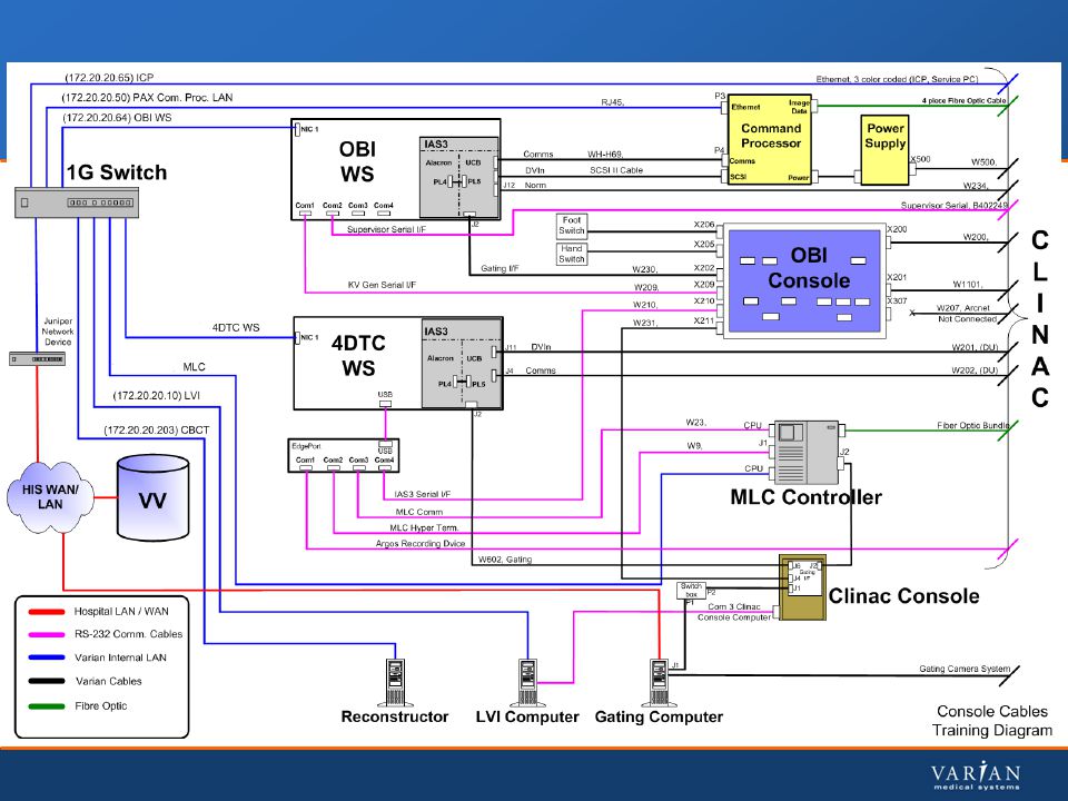
LOG Files During the treatment, the system can generate Logs: Clinac console (Communication/Log): Generation of a Dynamic beam delivery Log 4DITC WS : Generation of a MLC log (2 files Carriages A & B)
: Generation of a Dynamic beam delivery Log. 4DITC WS : Generation of a MLC log (2 files Carriages A & B)")
25
Dynamic MLC Arc log / Clinac Console
OOPS!! January 2008!!! It is Not a RapidArc or VMAT Log!!!

26
RapidArc - VMAT Log File / Clinac Console

27
MLC Log – Dynalog File Viewer
Dynamic leaf deviation Log Activation : Because DynaLog files are typically large, Varian recommends that this feature should be turned OFF, and only activated when there is a specific need for DynaLog files to be saved. DiagAutoDynalogs 2,1 for SW 6.8 DiagAutoDynalogs 1 for SW 7.x How to read?

28
MLC Log – Dynalog File viewer for SW6.8

29
MLC Log – Dynalog File viewer for SW7.x

30
MLC Log - Example

31
Control of the Dose rate
Fast beam-on / beam-off control. On high energy Clinac : the key is the triode gridded gun (On Unique system : magnetron frequency)
")
32
Control of the Dose rate
On high Energy Clinac the gridded electron gun allows Instantaneous dose rate control The cathode is heated to excite emissions of electrons. The injection is controlled by the grid.

33
Gridded GUN - HE Clinac - Injection OFF

34
Gridded GUN - HE Clinac - Injection ON

35
Gridded GUN HE Clinac The grid of the gun is used as an On/Off trigger which allows us to control the output electron emissions. A negative voltage is used to inhibit electron emissions and an approximately +160VDC pulse is used to allow the electrons to be released from the gun and into the guide. Gun is pulsed continuously for constant temperature and emission This gives us a very precise control so we can terminate or start the gun’s electron flow as required

36
Gridded GUN HE Clinac

37
Gridded GUN HE Clinac Injection pulses are coincident or delayed to RF pulses to produce beam pulses or not, based on the segments window.

38
Control of the Dose rate
RapidArc®. Quality Assurance. J. Bocanek 07/2009

39
Gun controller KLY Current signal Used as the pulse Reference
PULSE CONTROL GUN CONTROLLER KLY Current signal Used as the pulse Reference Constant time relationship to RF power in the guide.

40
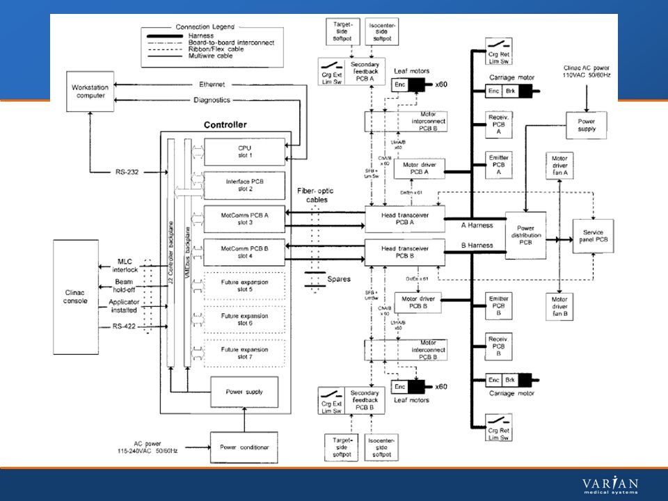
MLC The MLC workstation integrated in the 4DITC, sends data for entire treatment for all leaves, including dose versus position information, to MLC Controller via serial link MLC Controller will set MLC leaves in place Upon start of treatment, MLC Controller sends commands to MLC head via optical link to move leaves MLC Controller compares planned and actual position of each leaf obtained from feedback system with the treatment plan

42
MLC - Primary Readout System
Leaf Position is determined using 2 independent sources Primary Readout utilizes encoder mechanically attached to motor’s shaft for both carriages and leafs Carriage 540 counts = 1 mm of linear shift at isocenter Leaf 707 counts = 1 mm linear shift for full width leafs 512 counts = 1 mm linear shift for half width leafs at isocenter

43
MLC - Secondary Readout System / Interlock
Secondary Feedback verifies, that motor count really represents actual motion Carriage – Mylar strip with fine black lines at the side of carriage path is read by optical pair Leaf Secondary Feedback – Ceramic Ball (Wiper) on each leaf arm provides contact pressure on a “Soft Potentiometer” Interlock PRO/SPRO :The MLC Controller compares the Secondary position of the leaf (Soft Pot) to its primary position (Motor Encoder Counts)
 on each leaf arm provides contact pressure on a Soft Potentiometer Interlock PRO/SPRO :The MLC Controller compares the Secondary position of the leaf (Soft Pot) to its primary position (Motor Encoder Counts)")
44
Gantry rotation control
Prerequisite : From clutch drive to direct-drive Configuration - Clinac console SW &+ Clutchless drive & Velocity check enable Chain tightness Speed : Aerotech Motor Control board. It drives the motor with a Pulse width modulated 100VDC (60s -0/+3s)
")
45
Gantry rotation control – clutchless drive

46
RapidArc® delivery of the TrueBeam® accelerator. What’s different?

47
RapidArc® delivery of the TrueBeam accelerator compared to Clinac)
A TrueBeam system can deliver treatments up to 50% faster with a dose delivery rate of up to 2400 MU/min The TrueBeam delivers 'gated' RapidArc radiotherapy, which compensates for tumor motion by synchronizing imaging with dose delivery during a continuous rotation around the patient.

48
TrueBeam Overview The Truebeam is a full integrated sytem

49
Thank you for your interest and attention
Questions Discussion

50
Optimize RapidArc delivery – Technical aspect
Session 1b Optimize RapidArc delivery – Technical aspect Why a Machine QA ? Hardware and software adjustments (MLC – Gantry – Beam performance) PMI / (Tests, dynalog files) Discussion
 PMI / (Tests, dynalog files) Discussion.")
51
Optimize RapidArc delivery – Technical aspect
Why a specific Machine QA ? During RapidArc: MLC leaves are moving Gantry is rotating Dose rate is changing

52
Precision of the dose rate during gantry rotation ?
Many questions? Precision of the dose rate during gantry rotation ? Accuracy of gantry speed control ? Ability to accurately vary the MLC leaves speed ? Accuracy of the MLC leaves positions ? Gravity effect / gantry angle?

53
Article Commissioning - Machine QA

54
Machine QA – TPS / Patient QA

56
VMAT / RapidArc tests Sweeping gap ratio – Leaf gap Offset / dosimetry gap Picket fence (PF) Accuracy of DMLC position Static & during RapidArc DRGS : Ability to vary dose-rate and gantry speed 7 combinations of dose rate, gantry range and speed to give equal dose to each strip DRMLC : Ability to accurately vary MLC leaf speed and dose rate. 4 combinations of leaf speed and dose rate to give equal dose to each strip

57
Tests plans on MyVarian.com

58
Article on machine QA EPID-based
FOLLOWING ILLUSTRATIONS FROM THIS ARTICLE

59
Picket fence Test

60
DRGS Test

61
DRMLC Test

62
Technical approach / optimization
In a technical point of view what can we check ? The Mechanical performance (gantry, MLC) The Beam performance try to make a diagnostic in case of anomaly (beam or leaf related?) It is a separate approach, except for the absolute dosimetry calibration : Leaf Gap offset
 The Beam performance. try to make a diagnostic in case of anomaly (beam or leaf related ) It is a separate approach, except for the absolute dosimetry calibration : Leaf Gap offset.")
63
CTB-GE-725

64
The Mechanical performance (Clinac)
Gantry Isocenter check (Basic system QA) Chain correctly tightened (V7.11 & +). Check at few angles.
 Chain correctly tightened (V7.11 & +). Check at few angles.")
65
Gantry (Clinac) Bearing lubrification - every 2 years
Gantry well balanced? Check current (GAN MOTI - check the gain 6.45) Check “Auto Go” function (no stop short, no oscillation). AMC, 4 adjustments (current limit, loop back gain, offset, speed) 60s -0/+3s in both directions. If difference, check HCP / console Readout (PRO/SPRO). Replace the potmeters in case of frequent HWFA failures or “velocity check” errors. No backlash. Try to get the better “PRO calibration deviation” - Calibration
 Check Auto Go function (no stop short, no oscillation). AMC, 4 adjustments (current limit, loop back gain, offset, speed) 60s -0/+3s in both directions. If difference, check HCP / console. Readout (PRO/SPRO). Replace the potmeters in case of frequent HWFA failures or velocity check errors. No backlash. Try to get the better PRO calibration deviation - Calibration.")
66
The Mechanical performance (Clinac)
MLC Overview – main components Sources of error? Isocenter calibration (basic QA) Mechanical backlash (Leaves, carriages) Leaf speed response, kinetic properties MLC calibration Dynalog Viewer Hyperterminal Tests (Carriage & Leaves)
 Mechanical backlash (Leaves, carriages) Leaf speed response, kinetic properties. MLC calibration. Dynalog Viewer. Hyperterminal Tests (Carriage & Leaves)")
67
MLC - CTB-ML-422-F

68
MLC OVERVIEW

69
MLC OVERVIEW – main components

70
Carriage – Rails / bearing

71
Must be correctly tightened
MLC Carriages Must be correctly tightened

72
Motors interconnect

73
Motor / Encoder – Lead screw / bearing / T-nut

74
Leaf assembly T-nut Ceramic ball for sec readout Spring Drive screw
Motor Coupler

75
MLC Calibration

76
MLC Calibration

77
MLC Calibration Calibration is performed at the time of installation and after any discrepancies in leaf positioning are found An Alignment tool (10 mm metal bar) is attached to the Collimator to perform Calibration of the Leaf Banks An Infrared Optical beam in front of each carriage (when retracted) creates reference position for each leaf Encoder Counts (information representing linear move of the leaf) are referenced to the optical beam Calibration process. Differences SW version 6.8 / 7.x Mlcxcal.txt file (sw 6.8) diagAdjustSysOffsets command (sw 7.2+)
 is attached to the Collimator to perform Calibration of the Leaf Banks. An Infrared Optical beam in front of each carriage (when retracted) creates reference position for each leaf. Encoder Counts (information representing linear move of the leaf) are referenced to the optical beam. Calibration process. Differences SW version 6.8 / 7.x. Mlcxcal.txt file (sw 6.8) diagAdjustSysOffsets command (sw 7.2+)")
78
For rounded MLC leaf ends
MLC Calibration WARNING : don’t touch these parameters without knowing the consequences Skew Leaf Gap Light Radiation Leaf Gap For rounded MLC leaf ends Centerline

79
MLC Calibration Leaf Gap error / offset
This parameter is directly linked to the Dosimetry Leaf Gap (TPS). Round leaf edge introduces additional transmission through the tip of the leaves. In the TPS, it is considered as an apparent gap between 2 closed leaves with non rounded edge.
. Round leaf edge introduces additional transmission through the tip of the leaves. In the TPS, it is considered as an apparent gap between 2 closed leaves with non rounded edge.")
80
MLC Optical beam

81
Initialization Emitter gap 0.09mm A1 : Leading photodetector
From Jiri Bocanek / Varian Emitter gap 0.09mm A1 : Leading photodetector A2 : Trailing photodetector When the signal of the leading detector is 50% of the signal of the trailing detector, the optical receiver asserts the Leaf-at-cal signal. At this point the MLC controller monitors (counts) the motor encoder signals. If the trailing photodetector is not receiving light from the infrared emitter, something is blocking the beam and the optical receiver asserts a Leaf-in-field signal.
 the motor encoder signals. If the trailing photodetector is not receiving light from the infrared emitter, something is blocking the beam and the optical receiver asserts a Leaf-in-field signal.")
82
Measurement of the optical beam – Opto Receiver
MLC Optical beam WARNING : If adjustment or replacement of the emitter and/or the receiver are required, MLC leaf calibration, and therefore, MLC dose delivery could be affected Measurement of the optical beam – Opto Receiver TP1 to TP2 = A1 minus A2 TP2 to TP3 = A1 plus A2

83
Varian recommendations
MLC Optical beam CTB-ML-570 Varian recommendations Use the detector value (TP2-TP3) alone to determine when to change the emitter If the voltage (TP2-TP3) is less than 65mV, need emitter replacement and alignment. Always perform a full alignment procedure whenever any IR beam component is moved for any reason
 alone to determine when to change the emitter. If the voltage (TP2-TP3) is less than 65mV, need emitter replacement and alignment. Always perform a full alignment procedure whenever any IR beam component is moved for any reason.")
84
MLC Dynalog File Viewer
Use the Dynalog files as reference to monitor the wear of components. Check RMS data (average/Maximum/Histogram) ie : Use DLV, for the leaf speed test (acceptance of the RapidArc) or during other specific tests (QC).
 ie : Use DLV, for the leaf speed test (acceptance of the RapidArc) or during other specific tests (QC).")
85
Carriages : Varian recommendation (CTB-ML-422)
Annually - Carriage Backlash Test - Hyperterminal Command: ws 2 for SW6.8, ws for SW7.x) Collimator 0° Gantry rotation from 180° every 90° Collect Carriage A & B secondary readout from controller (1/100th of mm) Difference between High and low values # 10 Higher values indicate wear, or looseness of the primary bearing
 Collimator 0° Gantry rotation from 180° every 90° Collect Carriage A & B secondary readout from controller (1/100th of mm) Difference between High and low values # 10. Higher values indicate wear, or looseness of the primary bearing.")
86
Diagnostic commands Using the Hyperterminal Version 6.8 Software
Version 7.x Software diagPosILShow 2 diagPosILShow diagSecStatsShow 2 diagSecStatsShow diagMaxDeltaPriSecShow 2 diagMaxDeltaPriSecShow diagPriStallStatsShow 2

87
Leaf speed Each leaf speed should be similar to each other with a slight variation between the wider leaves and the thinner leaves Every leaf must meet a minimum speed of 2.5 cm/sec at isocenter (1,275 cm/sec at leaf plane) Initialize the MLC and run the PWM test Version 6.8 Software Version 7.x Software Initialize CTRL+x wr PWM command diagLeafPWMTestMlc 2 diagLeafPWMTestMlc
 Initialize the MLC and run the PWM test. Version 6.8 Software. Version 7.x Software. Initialize. CTRL+x. wr. PWM command. diagLeafPWMTestMlc 2. diagLeafPWMTestMlc.")
88
Leaf speed - PWM Test If PWM < 12 for full leaves or PWM < 22 for half leaves, then no action is required If PWM > 35 for full or half leaves, then cleaning or other service is required If PWM is in between these values, then particular attention should be paid to leaves with significantly different values than the average.

89
Leaf speed - PWM Test High PWM values typically require leaf cleaning and/or leaf train component replacement. Adjacent pairs of leaves Dirty leaves Individual leave Drive train component pb (excessive wear of the motor, drive screw…etc) Note : Higher PWM values (up to 2x) may be seen with CLL motors ( and ). Grey color cables, instead of black. Try to save all these diagnostic tests data for future comparison
 Note : Higher PWM values (up to 2x) may be seen with CLL motors ( and ). Grey color cables, instead of black. Try to save all these diagnostic tests data for future comparison.")
90
Leaf Backlash test Position the gantry in the head-down position
In Hyperterminal, run the following applicable diagnostic commands Version 6.8 Software Version 7.2 Software diagLeafBacklashAll 2,1 (carriage A) diagLeafBacklashAll 1 (carriage A) diagLeafBacklashAll 2,2 (carriage B) diagLeafBacklashAll 2 (carriage B)
 diagLeafBacklashAll 1 (carriage A) diagLeafBacklashAll 2,2 (carriage B) diagLeafBacklashAll 2 (carriage B)")
91
Leaf Backlash Analyze the backlash values in the first column after the leaf numbers. Any values >0.200 require service. This typically requires leaf T-nut replacement

92
Statistical Data Analysis

93
Leaf Touch Test – SW 7.x After a successful initialization, observe the Touch Test results at the bottom of the Hyper Terminal screen. Verify leaf gap values are less than +/ mm. If any of the leaf gap values are >+/-0.20 mm, the MLC system requires a realignment. Leaf gap errors >0.30 mm will result in initialization failures.

94
Beam performance Machine QC: In case of an anomaly with DRGS, or DRMLC tests All leaves? Beam or carriage? Beam quality – main parameters to control High voltage (PFN / HVPSI) PFN servo Gun emission (GunI) Hyper Frequency power (RF driver and AFC) AFC servo (no limitation on AFC, good system temperature) FWRPW / KLYI / Target current - flat shapes
 PFN servo. Gun emission (GunI) Hyper Frequency power (RF driver and AFC) AFC servo. (no limitation on AFC, good system temperature) FWRPW / KLYI / Target current - flat shapes.")
95
Beam performance A good STARTUP of the beam is important.
Dose rate stability % with and w/o the PFN servo Dosimetry / POS & ANG servos No difference of DR with close and open loops. Field light / Xray beam correct with closed loops Gantry rotation : No loss of DR (DR servo open)
")
96
Thank you for your interest and attention
Questions Discussion

Similar presentations