Download presentation
Presentation is loading. Please wait.

1
DOPPLER ECHOCARDIOGRAPHY-1
BASIC PHYSICS,PULSE WAVE AND CONTINUOS WAVE DOPPLER DR PRADEEP SREEKUMAR

2
Sound is a mechanical vibration transmitted through an elastic medium
Ultrasound-portion of sound spectrum having frequency greater than 20,000 cycles /sec Use of ultrasound to study the structure and function of heart and great vessels-echocardiography Advantages of ultrasound Can be directed as a beam and focussed Obeys laws of reflection and refraction Produce longitudnal waves

3
Generation Of An Ultrasound Image

6
Machines There are 5 basic components of an ultrasound scanner that are required for generation, display and storage of an ultrasound image. Pulse generator - applies high amplitude voltage to energize the crystals Transducer - converts electrical energy to mechanical (ultrasound) energy and vice versa Receiver - detects and amplifies weak signals Display - displays ultrasound signals in a variety of modes Memory - stores video display
 energy and vice versa. Receiver - detects and amplifies weak signals. Display - displays ultrasound signals in a variety of modes. Memory - stores video display.")
7
Depicted as sine wave-peaks and troughs
One cylce=one compression + one rarefaction Distance between 2 similar points represent wavelength 0.15 to 1.5 mm in soft tissue Frequency- number of wavelengths per unit time V=f X λ(v=velocity,f =frequency, λ is wavelength)
")
8
Velocity of sound=1540 m/sec in soft tissue
Wavelength=1.54/f Amplitude Measure of strength of the sound wave Indicated by height of sine wave above and below baseline

11
Higher the frequency greater the resolution
Higher frequency,lesser the penetration Loss of ultrasound as it propogates through a medium is called attenuation

12
PRICIPLES OF PEIZO ELECTRIC CRYSTALS
The charges in a piezoelectric crystal are exactly balanced, even if they're not symmetrically arranged. The effects of the charges exactly cancel out, leaving no net charge on the crystal faces the electric dipole moments—vector lines separating opposite charges—exactly cancel one another out. If you squeeze the crystal , you force the charges out of balance.

13
Now the effects of the charges (their dipole moments) no longer cancel one another out and net positive and negative charges appear on opposite crystal faces. By squeezing the crystal, voltage is produced across its opposite faces- piezoelectricity The piezoelectric effect was discovered in 1880 by two French physicists, brothers Pierre and Paul-Jacques Curie, in crystals of quartz, tourmaline, and Rochelle salt (potassium sodium tartrate). They took the name from the Greek work piezein, which means "to press."
. They took the name from the Greek work piezein, which means to press.")
14
The phenomenon of generation of a voltage under mechanical stress is referred to as the direct piezoelectric effect mechanical strain produced in the crystal under electric stress is called the converse piezoelectric effect.

15
Ferro electrics,barium tianate,lead zirconate titanate are used as peizo electric crystals.
Dampening material-shortens the ringing response Also absorbs backward and laterally transmitted acoustic energy Frequency emitted by transducer is directly proportional to propagation speed within crystal and inversely related to thickness

16
Important feature of ultrasound is ability to direct or focus the beam as it leaves the transducer
Proximal cylindrical and distally divergent Proximal zone –Fresnel zone Divergent field is called Fraunhofer zone Imaging is optimal in near field Decreasing wavelength or increasing transducer size increase near field

18
Haemo”dynamics” Blood flow is a complex phenomenon
Not a uniform liquid Flow pulsatile Vessel walls are elastic

19
Properties of Blood Density-mass of blood per unit volume
Measure of resistance to accelaration Greater the density,greater the resistance to flow Viscosity:resistance to flow offered by fluid in motion 0.035 poise at 37 degree.

21
Factors determining flow
Flow rate is determined by Pressure gradient Resistance Viscosity of blood Radius of lumen Length of vessel

22
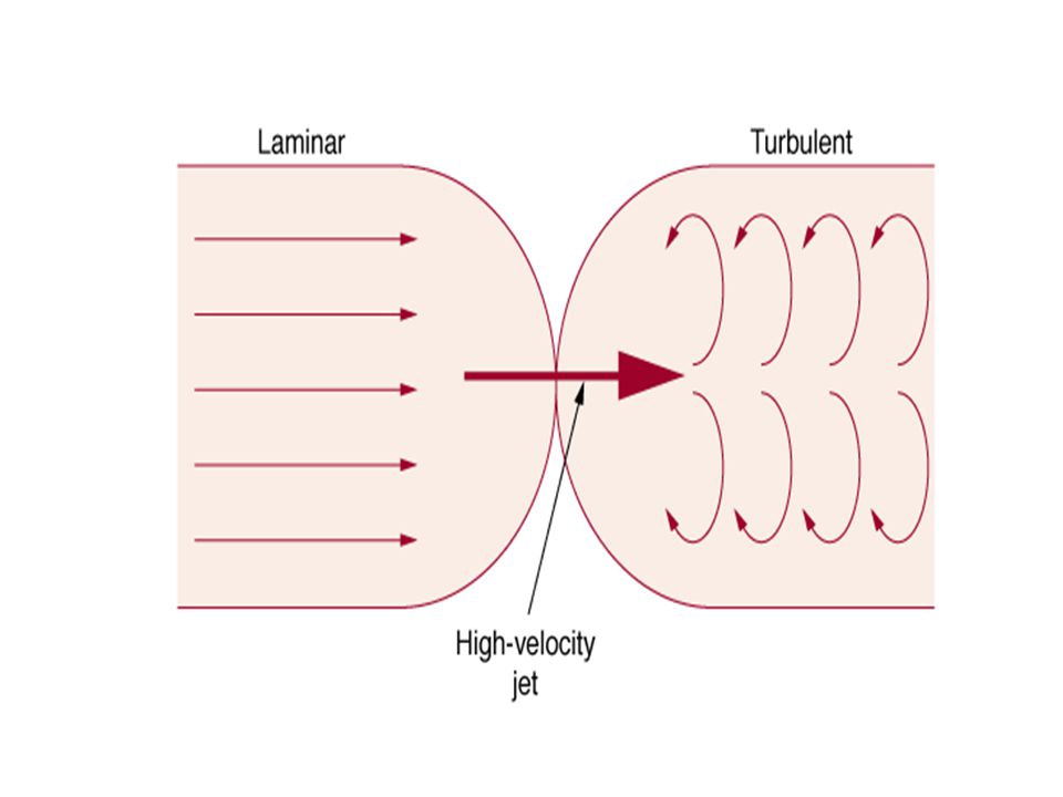
Types of flow Laminar flow Shape of parabola
Concentric layers,each parallel to vessel wall Velocity of each layer differs Maximal velocity is at centre of vessel Decreasing profile towards peripheries

26
Turbulent flow Obstruction produce increased velocities, flow vortices
Whirlpools shed off in different directions producing variable velocities- chaos Predicted by Reynolds number Reynolds number depends on Re=( ρ x c x D)/v ρ-Density of blood D-Vessel diameter c-Velocity of flow V-viscosity
/v. ρ-Density of blood. D-Vessel diameter. c-Velocity of flow. V-viscosity.")
27
The Reynolds number is dimensionless
If Re is less than 1200 the flow will be -laminar flow is described as -transitional Greater than turbulent

28
Doppler Principle

29
First described by Johann Christian Doppler, an Austrian mathematician and scientist who lived in the first half of the19th century. Doppler’s initial descriptions referred to changes in the wavelength of light as applied to astronomical events. In 1842, he presented a paper entitled "On the Coloured Light of Double Stars and Some Other Heavenly Bodies" where he postulated that certain properties of light emitted from stars depend upon the relative motion of the observer and the wave source.

30
Doppler effect describes the frequency shift of the signal in relation to the relative motion of a source and an observer. The wave generated by a source that moves away from an observer/receiver appears to him to be of lower frequency than the wave generated by a stationary source, or generated by a source moving toward the observer. The frequency of the signal detected by the receiver moving toward the still source is higher, compared to the frequency detected by the still receiver, or a receiver moving away from the source.

31
Applied in echocardiography to determine flow direction,flow velocities,flow characteristics
Stationary rbc-zero doppler shift(received frequency= transmitted frequency) Positive doppler shift-RBCs moving towards transducer ,received frequency >transmitted frequency Negative doppler shift:RBC’s moving away from transducer- transmitted frequency more than receiving frequency
 Positive doppler shift-RBCs moving towards transducer ,received frequency >transmitted frequency. Negative doppler shift:RBC’s moving away from transducer- transmitted frequency more than receiving frequency.")
33
Doppler shift represents difference between received and transmitted frequencies ,which occur due to motion of RBC’s relative to the ultrasound beam Fd = (2f V cos Ø)/C
/C.")
34
Why the factor 2? Double doppler shift
1st shift-transducer stationary source,RBC the moving receiver 2nd shift is when,RBCs are moving source and transducer is the stationary receiver.

35
Doppler equation- rearranged

36
Factors affecting doppler equation
Estimation of blood flow velocity is dependent on incident angle between ultrasound beam and blood flow When RBCs parallel-maximum velocity When RBCs perpendicular-no doppler shift When angle between ultrasound beam and blood flow is less than or equal 20 degree,cosine close to 1 and percent error is less than or equal to 7%

37
The Effect of Angle

38
Angle Cosine Percentage error 0 1 0 10 0. 98 2 20 0. 94 7 30 0

39
Angle correction It is possible to correct for angle
Not recommended as in most cases its possible to align ultrasound beam parallel by utilising multiple views, serial assessment difficult unless same angle correction used It is assumed that angle between ultrasound beam and direction of blood flow is parallel

40
By adjusting according to the direction of assumed flow, it changes the angle calculations in the Doppler equation resulting in different estimates of flow velocity. The use of this control does not actually change the direction of the Doppler beam and its use does not alter the quality of either the audio output or the spectral recording

41
Effect of frequency Lower the frequency,higher the velocity detected
A 2 MHz transducer detects higher velocity compared to a 5 MHz transducer

42
SPECTRAL DOPPLER DISPLAY
Flow velocity Displayed on y axis Velocity of RBCs within sampled volume is calculated Absence of velocity-zero baseline

43
Spectral velocity recordings

44
Direction of flow Flow direction also displayed on Y axis
Positive doppler shift-flow towards transducer Traditionally displayed above baseline Negative doppler shift-flow away from transducer Displayed below zero baseline

45
Intensity or amplitude
Blood cells do not move at equal velocities Produce different frequency shifts Amplitude or intensity of doppler signal reflects number of blood cells moving within a range of velocities at a particular point of time Bright signal-strong doppler shift frequency at a particular point of time . Darker regions-weak doppler shift

46
Timing Time is displayed along x axis Displayed along with ECG.
Change in blood velocity,flow direction can be accurately timed in relation to cardiac cycle.

47
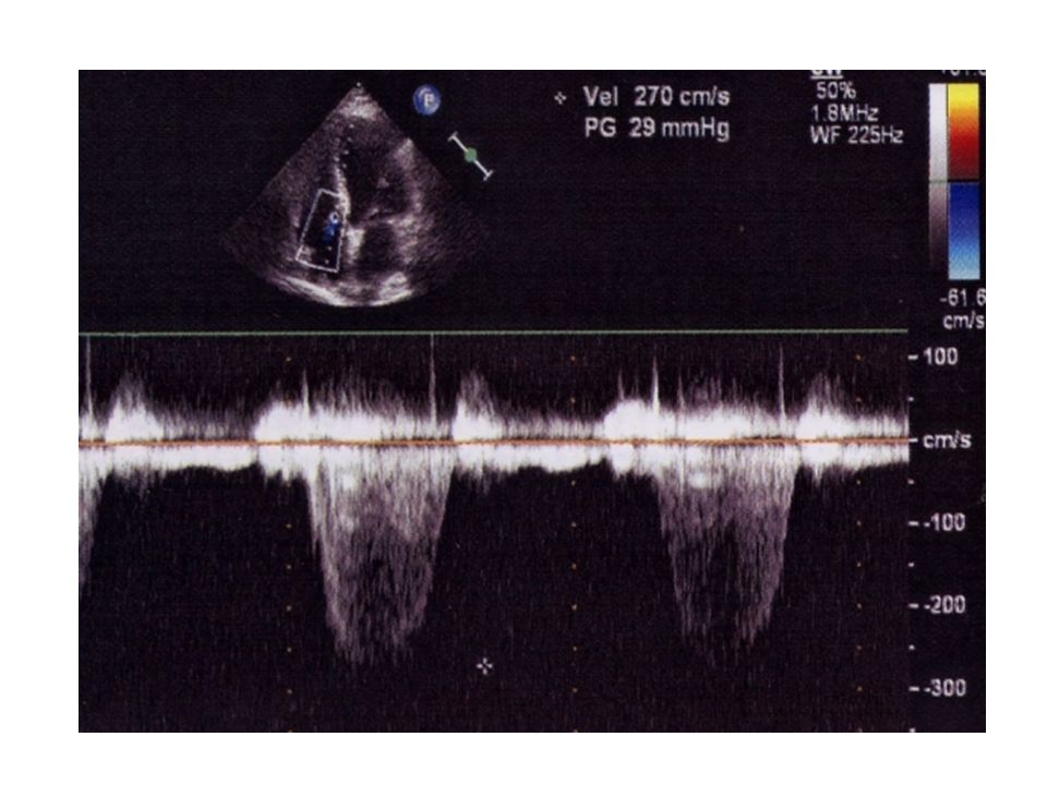
Doppler Audio signals Doppler shift frequencies are in audible range
Guide for localising blood flow and for proper aligning ultrasound beam parallel to flow Laminar flow-smooth tone Turbulent flow-harsh sound.

48
Pulsed and Continuous Wave Doppler

50
Continuous Wave Doppler
older and electronically more simple continuous generation of ultrasound waves continuous ultrasound reception two crystal transducer Blood flow along entire beam is observed Continuous Wave Doppler

52
ADVANTAGE ability to measure high blood velocities accurately DISADVANTAGE 1)lack of selectivity or depth discrimination 2)no provision for range gating to allow selective placing of a given Doppler sample volume in space
no provision for range gating to allow selective placing of a given Doppler sample volume in space.")
53
Pulsed Wave Doppler Ultrasound impulses are sent out in short bursts or pulses transducer that alternates transmission and reception of ultrasound ability to provide Doppler shift data selectively from a small segment along the ultrasound beam- sample volume can be selected.

54
The transducer functions as receiver for a limited time period
Time corresponds to the interval required for sound to return from specified area. Another burst of sound waves are not transmitted until previous impulses are received. Pulse repetition frequency (PRF)–frequency at which transducer transmits pulses. PRF determines sampling rate.
–frequency at which transducer transmits pulses. PRF determines sampling rate.")
56
Inability to accurately measure high blood flow velocities- aliasing
“Alias” means false

57
Aliasing The aliasing phenomenon occurs when the velocity exceeds the rate at which the pulsed wave system can record it properly Fig.1.24

59
Aliasing is represented on the spectral trace as a cut-off of a given velocity with placement of the cut section in the opposite channel or reverse flow direction

60
Nyquist Limit The Nyquist limit defines when aliasing will occur using PW Doppler. The Nyquist limit specifies that measurements of frequency shifts (and, thus, velocity) will be appropriately displayed only if the pulse repetition frequency (PRF) is at least twice the maximum velocity (or Doppler shift frequency) encountered in the sample volume.
 will be appropriately displayed only if the pulse repetition frequency (PRF) is at least twice the maximum velocity (or Doppler shift frequency) encountered in the sample volume.")
62
The Nyquist Limit The simplest sound wave is an oscillation between two amplitudes. A sampled waveform thus needs at least two sample points per cycle. Thus the wave's frequency must not be above half the sampling frequency. This limit is called the Nyquist limit of a given sampling frequency

63
Shannon's sampling theorem
(Claude E. Shannon, born 1916, American mathematician) Also known as the Nyquist criterion, a general "rule" for measurement of frequencies, stating that the measurement (sampling) frequency must be at least twice the maximum frequency to be measured. Whenever Shannon's sampling theorem is not fulfilled, aliasing occurs
 Also known as the Nyquist criterion, a general rule for measurement of frequencies, stating that the measurement (sampling) frequency must be at least twice the maximum frequency to be measured. Whenever Shannon s sampling theorem is not fulfilled, aliasing occurs.")
64
Nyquist limit specifies the maximum velocity that can be recorded without aliasing.

65
Avoiding aliasing Increase the Nyquist limit- 1)altering variables in Doppler equation 2)high PRF mode 3 )Change from PW to CW
altering variables in Doppler equation 2)high PRF mode 3 )Change from PW to CW")
66
V = C × PRF 4 f COS Ø (PRF= Δf× 2= 2f V cos Ø × 2) C Max velocity can be increased by 1)Increasing PRF 2)Decreasing transmitted frequency 3)Increasing speed of sound in tissue 4)Decreasing cosØ
Increasing PRF. 2)Decreasing transmitted frequency. 3)Increasing speed of sound in tissue. 4)Decreasing cosØ.")
67
High PRF Doppler

68
It is desirable to use as high a PRF as possible for recording abnormally elevated velocity jets.
Maximum PRF is limited by the distance the sample volume is placed into the heart.

69
Range ambiguity some of the range selectivity used in precisely locating the sample volume is lost. pulsing sequence is carried on over and over, some data is returned to the transducer data from all these volumes are added together

70
Baseline shift ("zero shift" or "zero off-set" )
Electronic cut and paste Moves the aliased doppler signal upward or downward(unwrapping) Repositioning baseline effectively increases the maximum velocity at the expense of other direction.
 Repositioning baseline effectively increases the maximum velocity at the expense of other direction.")
71
"baseline shift"

72
Pulse Wave VS Continuous Wave Doppler
CW PW Depth resolution no yes Sample volume large small High velocity detection yes no Aliasing no yes Sensitivity more less Control of sample volume placement poor good

73
Continuity equation The continuity equation states that the amount of blood flow through one cardiac chamber (or valve orifice) is the same as the blood flow through the other chambers and orifices It is based on the principle of conservation of mass. “Whatever mass flows in must flow out.”
 is the same as the blood flow through the other chambers and orifices. It is based on the principle of conservation of mass. Whatever mass flows in must flow out.")
74
The Continuity Equation

75
VELOCITY TIME INTEGRAL
Calculation of volumetric flow is complex as flow velocity is not constant Blood flow is pulsatile Hence integrated velocity over time is taken VTI is equal to area under curve cm/sec X sec. Measure of distance that blood moves with each heart beat. VTI is also referred to as “stroke distance”

77
Volumetric flow or stroke volume can be thus calculated as
SV=CSA X VTI Continuity equation can be rewritten as- CSA1 X VTI 1=CSA2 X VTI 2 CSA2 =(CSA1 x VTI 1) /VTI 2
 /VTI 2.")
78
VTI is obtained by tracing the leading edge of velocity spectrum.

79
Clinical Applications
Calculation of valve areas Calculation of regurgitant volumes and fractions Calculation of regurgitant orifice areas Calculation of intra cardiac shunt ratios

80
LIMITATIONS OF CONTINUITY PRINCIPLE
Erroneous determination of CSA Measurement of diameter during wrong phase of cardiac cycle. Inconsistent annulus measurements Erroneous determination of VTI Incorrect placement of pulse wave sample volume Significant angle between doppler beam and blood flow Incorrect filter/gain settings

81
Bernoulli's principle is named after Swiss mathematecian Daniel Bernoulli who published his principle in his book Hydrodynamica in 1738

82
Bernoulli equation Bernoulli described the conversion of energy in a fluid from one form to another, as occurs when fluid flow in a tube that suddenly either increases or decreases its diameter. Bernoulli's law states that total energy at all points along a tube is the same—conservation of energy. Energy (the ability to do work) is composed of pressure energy (pressure x the volume of fluid),kinetic energy (fluid in motion has kinetic energy ,which is proportional to the mass and the velocity squared; mass is density x volume), and gravitational energy (the product of density, volume, height above a surface, and the gravitational constant).
 is composed of pressure energy (pressure x the volume of fluid),kinetic energy (fluid in motion has kinetic energy ,which is proportional to the mass and the velocity squared; mass is density x volume), and gravitational energy (the product of density, volume, height above a surface, and the gravitational constant).")
85
Limitations of Bernoulli Equation
Significant flow acceleration-prosthetic valves Significant viscous forces-muscular VSD,tunnel subaortic stenosis Increased proximal velocity-AS+AR,AS + HOCM Altered blood viscosity-polycythemia

86
Discrepancies between Catheter derived and Doppler derived Pressure Gradients
Pressure gradients derived at cardiac cathetrisation and measured by Doppler may differ. Catheter derived gradient is peak to peak gradient between LV and Aorta Non simultaneous measurement Doppler gives peak instantaneous gradient and is greater than peak to peak gradient.

87
PRESSURE RECOVERY PHENOMENON
Complex hemodymanic concept- pressure of fluid decreases as velocity increases. Once flow passes through a narrowing pressure drops and increases towards original value Rate and magnitude of pressure recovery is variable In prosthetic valves,3 effective orifices-2 large orifices by sides and a central small orifice. Maximum velocity and lowest pressure is at narrowest orifice.

88
Immediately distal to orifice, pressure increases (recovers)and velocity decreases.
Doppler gradients are measured at narrowest orifice, while catheter gradients are recorded downstream to prosthetic valve where the pressure has already recovered. Hence, Doppler derived pressure gradients are more compared to catheter derived pressure gradients.

90
Determination of Pressure Gradients
Pressure gradients are useful for assessment of severity of valvular stenosis and estimation of intracardiac pressures . Pressure gradients commonly determined by Doppler include 1)Maximum instantaneous pressure gradient 2)Mean pressure gradient
Maximum instantaneous pressure gradient. 2)Mean pressure gradient.")
91
Maximum Instantaneous pressure gradient =4v2
(v=peak velocity) Mean pressure gradient cannot be obtained from the mean (or average) velocity, but must be calculated by making multiple instantaneous gradient (and hence pressure calculations) measurements, and then averaging those instantaneous pressures.
 Mean pressure gradient cannot be obtained from the mean (or average) velocity, but must be calculated by making multiple instantaneous gradient (and hence pressure calculations) measurements, and then averaging those instantaneous pressures.")
93
Estimation of RVSP by TR
TR doppler signal represents the pressure difference between RV and RA during Systole RVSP-RAP=4(V TR 2 ) In absence of RVOT obstruction RVSP=Pulmonary artery systolic pressure.
 In absence of RVOT obstruction. RVSP=Pulmonary artery systolic pressure.")
95
RVSP= BP SYSTLOLIC -4(V vsd )2
2")
96
PASP=BP SYSTOLIC -4(V PDA )2
2")
97
Mean Pulmonary Artery Pressure=4 (V PR-PEAK)2
2")
98
PAEDP=4 (V PR-ED)2 + RVEDP
2 + RVEDP")
99
LAP= BP SYSTOLIC -4 (V MR)2
2")
100
LVEDP =BP DIASTOLIC - 4 (V AR-ED)2
2")
101
Pressure half-time and deceleration time
The pressure half-time (PHT) is defined as the time (in milliseconds) required for the peak initial pressure to drop by one half . Doppler signal measures velocity The modified Bernoulli equation is applied to convert velocity to pressure. PHT is the time (in milliseconds) for the velocity to drop to of the maximum velocity . V2 = (0.707) x V1
 is defined as the time (in milliseconds) required for the peak initial pressure to drop by one half . Doppler signal measures velocity. The modified Bernoulli equation is applied to convert velocity to pressure. PHT is the time (in milliseconds) for the velocity to drop to of the maximum velocity . V2 = (0.707) x V1.")
103
The DT is the time required for the velocity,beginning with the peak value, when extrapolated, to cross the zero baseline The PHT is clinically used most frequently in evaluating mitral stenosis and aortic regurgitation

105
MVA = 220/PHT PHT = 0.29 xDT MVA =220/0.29 x DT =759/DT

106
Limitations of PHT in calculation of MVA
Non linear early diastolic slope Post balloon mitral valvuloplasty Significant Aortic regurgitation Cardiac rhythm disturbances

107
Non linear early diastolic slope
Non linear or curvilinear decay –lead to erroneous calculation of PHT. Part of slope considered most representative should be chosen.

108
Post balloon mitral valvuloplasty
Accuracy of calculated MVA by PHT declines immediate post BMV. PHT is directly related to chamber compliance and peak transmitral gradient Following BMV,abrupt changes in left atrial pressure and compliance occur altering the relationship between PHT and Mitral valve area. This effect on PHT lasts 24 to 48 hours.

109
Significant Aortic regurgitation
Severe AR shortens PHT. This is due to markedly elevated LVEDP which reduces diastolic pressure gradient between LA and LV. Mitral valve area is thus overestimated.

110
Cardiac rhythm disturbances
Tachycardia-deceleration slope is shortens,PHT shortens and thus valve area is overestimated.

111
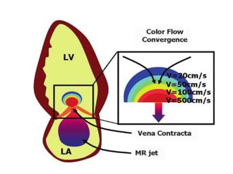
Proximal Isovelocity Surface Area (PISA)
Proximal Isovelocity Surface Area (PISA) method is based on the continuity equation. When a flow passes through a narrow orifice, as it approaches the narrowest region, there is a flow convergence and flow acceleration. PISA is the surface area of the hemisphere at the aliasing region of the flow convergence. PISA increases with lower aliasing velocity.
 method is based on the continuity equation. When a flow passes through a narrow orifice, as it approaches the narrowest region, there is a flow convergence and flow acceleration. PISA is the surface area of the hemisphere at the aliasing region of the flow convergence. PISA increases with lower aliasing velocity.")
114
Radius is measured from the orifice to point of colour change.
If the flow convergence is not a true hemisphere, the angle subtended by the flow convergence at the orifice has to be measured and divided by 180 to get a correction . Good correlation between angiographic estimates of regurgitant flow and PISA based estimates have been reported.

115
Valve area calculation
A0=(2 Л r2x VN)/V0 A0=area of narrowed orifice V0=velocity at narrowed orifice R=radius of shell VN=aliased velocity identified as Niquist limit
/V0 A0=area of narrowed orifice V0=velocity at narrowed orifice R=radius of shell VN=aliased velocity identified as Niquist limit")
116
Angle correction PISA principle is for flow approaching narrow planar surface In Mitral Stenosis,mitral leaflets may be funnel shaped To account for altered shape,angle corection factor ά /180 is applied. MVA= ( ά /180 ) x (2 Л r2x VN)/VMS
 x (2 Л r2x VN)/VMS")
118
Limitations of PISA method
Errors in measurement of radius Valve area is proportional to square of radius-even small errors are magnified. Errors in measurement of angle Measurement is done offline using a protractor Angle measured in one dimension may not be true representation of valve leaflet geometry.

119
THANK YOU

120
MCQs

121
Maximum detectable velocity for a 5 MHz probe ,(assuming Doppler shift frequency as 5 KHz ,speed of sound in tissue as 1500m/sec and doppler beam being parallel to blood flow) ,would be a)0.62 m/sec b)0.75 m/sec c)0.92 m/sec d)1.0 m/sec
 ,would be a)0.62 m/sec b)0.75 m/sec c)0.92 m/sec d)1.0 m/sec")
122
Percentage error when ultrasound beam makes an angle of 20 degrees to blood column a)3 b)7 c)15 d)30
3 b)7 c)15 d)30")
123
When frequency of ultrasound probe is reduced, a)Resolution increases b)Maximum detectable velocity increases c) Attenuation increases d)All of the above
Resolution increases b)Maximum detectable velocity increases c) Attenuation increases d)All of the above")
124
Following statements are true about pulse wave doppler compared to continuous wave doppler except a)Better depth resolution b)Larger sample volume c)More problem of aliasing d) Less sensitivity
Better depth resolution b)Larger sample volume c)More problem of aliasing d) Less sensitivity")
125
Resistance to flow through a tube is directly proportional to
a)Fourth power of radius b)Second power of radius c)Length of tube d)None of the above
Fourth power of radius. b)Second power of radius. c)Length of tube. d)None of the above.")
126
Turbulent flow typically occurs when reynolds number just exceeds

127
Pulse wave is preferred to continuous wave doppler to assess flow in all except a)Pulmonary vein b)Superior venacava c)Pulmonary valve d)Aortic valve
Pulmonary vein b)Superior venacava c)Pulmonary valve d)Aortic valve")
128
Doppler shift is directly proportional to all except a)Speed of sound in tissue b)Velocity of blood flow c)Frequency of transducer d)Cosine of angle between interrogating beam and blood flow
Speed of sound in tissue b)Velocity of blood flow c)Frequency of transducer d)Cosine of angle between interrogating beam and blood flow")
129
True about Mitral valve area assessment by PHT in severe AR is a)PHT increases b)Valve area is underestimated c)MS severity is underestimated d)Increases diastolic gradient between LA and LV.
PHT increases b)Valve area is underestimated c)MS severity is underestimated d)Increases diastolic gradient between LA and LV.")
130
Mean pulmonary artery pressure of a patient with TR jet velocity of 3 m/sec, Peak PR velocity of 2m/sec is (in mm Hg) a)36 b)16 c) 9 d)20
 a)36 b)16 c) 9 d)20")
131
KEY

132
Maximum detectable velocity for a 5 MHz probe ,assuming Doppler shift frequency as 5 KHz ,speed of sound in tissue as 1500m/sec and doppler beam being parallel to blood flow, would be a)0.62 m/sec b)0.75 m/sec c)0.92 m/sec d)1.0 m/sec
0.62 m/sec b)0.75 m/sec c)0.92 m/sec d)1.0 m/sec")
133
Percentage error when ultrasound beam makes an angle of 20 degrees to blood column a)3 b)7 c)15 d)30
3 b)7 c)15 d)30")
134
When frequency of ultrasound probe is reduced, a)Resolution increases b)Maximum detectable velocity increases c) Attenuation increases d)All of the above
Resolution increases b)Maximum detectable velocity increases c) Attenuation increases d)All of the above")
135
Following statements are true about pulse wave doppler compared to continuous wave doppler except a)Better depth resolution b)Larger sample volume c)More problem of aliasing d) Less sensitivity
Better depth resolution b)Larger sample volume c)More problem of aliasing d) Less sensitivity")
136
Resistance to flow through a tube is directly proportional to
a)Fourth power of radius b)Second power of radius c)Length of tube d)None of the above
Fourth power of radius. b)Second power of radius. c)Length of tube. d)None of the above.")
137
Turbulent flow typically occurs when reynolds number just exceeds

138
Pulse wave is preferred to continuous wave doppler to assess flow in all except a)Pulmonary vein b)Superior venacava c)Pulmonary valve d)Aortic valve
Pulmonary vein b)Superior venacava c)Pulmonary valve d)Aortic valve")
139
Doppler shift is directly proportional to all except a)Speed of sound in tissue b)Velocity of blood flow c)Frequency of transducer d)Cosine of angle between interrogating beam and blood flow
Speed of sound in tissue b)Velocity of blood flow c)Frequency of transducer d)Cosine of angle between interrogating beam and blood flow")
140
True about Mitral valve area assessment by PHT in severe AR is a)PHT increases b)Valve area is underestimated c)MS severity is underestimated d)Increases diastolic gradient between LA and LV.
PHT increases b)Valve area is underestimated c)MS severity is underestimated d)Increases diastolic gradient between LA and LV.")
141
Mean pulmonary artery pressure of a patient with TR jet velocity of 3 m/sec, Peak PR velocity of 2m/sec is (in mm Hg) a)36 b)16 c) 9 d)20
 a)36 b)16 c) 9 d)20")
Similar presentations


 Continuous Wave 2) Pulse Wave 3) Color Flow DOPPLER ULTRASOUND.>")


 is the fundamental alternating current (ac) and alternating voltage waveform. Electrical sine waves are.>")


