Download presentation
Presentation is loading. Please wait.

1
Welcome to Fired Heater Training!
The course is designed to give you some background information needed to operate a fired heater

2
Agenda Introduction Air/Fuel Ratios Fundamentals of Burners
Fundamentals of Furnaces Furnace Tuning and Use of Analyzer NOx and Advanced Burner Design Field Tuning of Heaters Q & A and Wrap-up

3
Heater and Burner Operation

4
Course Objective To ensure that everyone fully understands how burners and heaters work.

5
Course Topics Combustion Essentials Basic Burner Designs Furnace Types
Draught Heater Tuning Low NOx Burner Designs

6
Combustion Essentials

7
What is Combustion? A chemical reaction between fuel and oxygen producing heat. Air is usually the source of oxygen. The chemical reaction produces “flue gases”

8
What Is Required For Combustion?
Three Elements: Fuel Air Source of Ignition

9
Fuel Components Gas, Oil and Coal are all basically a mix of Hydrocarbons. During combustion these break down progressively as some parts burn more easily. The most important components are Carbon and Hydrogen compounds.

10
Other Components In addition to the Carbon and Hydrogen many fuels contain Sulphur. Sulphur also burns but produces hazardous products. Liquid and solid fuels can contain other non-combustibles which form ash. Nitrogen may be present as a gas or in compound form in liquid/solid fuels.

11
Chemical Formulas In formulas we will use the following basic components Carbon = C Hydrogen = H2 Oxygen = O2 Nitrogen = N2 Water = H2O Carbon Dioxide = CO2 Methane = CH4

12
Note on Calculations Each component in a formula is a Molecule (of gas) A Molecule of any gas occupies the same Volume The number of Molecules is therefore the same as the number of Volumes All calculations are therefore Volumetric, including measured Gas Analyses e.g. 2 CO = 2 volumes of CO

13
Examples Of Combustion For Typical Fuel Components with Oxygen
C + O2 ® CO2 2H2 + O2 ® 2H2O S + O2 ® SO2

14
Heat Where does the heat come from? Heat + C + O CO2

15
But we don’t have Pure Oxygen available
Oxygen in Air (by volume) Air ≈ 21% O2 + 79% N2 Ratio 1 O2 : 3.75 N2 The other main component in air is Water Vapour. In humid conditions this can be 5% or more and affects efficiency
 Air ≈ 21% O2 + 79% N2. Ratio. 1 O2 : 3.75 N2. The other main component in air is Water Vapour. In humid conditions this can be 5% or more and affects efficiency.")
16
Examples Of Combustion For Basic Fuel Components with Air
C + O N2 ® CO N2 2H2 + O N2 ® 2H2O N2 S + O N2 ® SO N2

17
Example - Combustion Of Methane
CH4 + 2O N CO2 + 2H2O + 7.5N2 + Heat

18
Stoichiometry The technical term used to define the theoretical amount of air or oxygen required for complete combustion of a fuel is the Stoichiometric ratio. e.g. - for a typical Natural Gas the Stoichiometric Ratio is approximately 10 volumes of Air to one of Gas.

19
Excess Air Because of many factors, including imperfect mixing, extra air is always needed to ensure complete combustion. The extra air above the Stoichiometric amount required is known as the excess air.

20
Stoichiometric Air Example
CH4 + 2O N2 ® CO2 + 2H2O + 7.5N2 + Heat Note – no Excess Oxygen in Flue Gas

21
Excess Air Example CH4 + ( )O2 + ( )N2 CO2 + 2H2O + 9N O2 + Heat 0.4/2.0 = 0.2 or 20% excess air 0.4/( )=0.032 or 3.2%O2 in flue gases (wet) 0.4/( )=0.038 or 3.8%O2 (dry)
=0.032 or 3.2%O2 in flue gases (wet) 0.4/( )=0.038 or 3.8%O2 (dry)")
22
Fuel Rich Examples (Sub-stoichiometric)
3C + O2 2 CO + C + heat 4H2 + O2 2 H2O + 2H2 + heat Products include Combustible Gases and free Carbon (soot)
")
23
Some Dangers of operating below Stoichiometric
Flue gases contain combustibles. When these gases find a supply of air they will burn. If this happens in the convection tubes it can damage the tubes. Pockets of gas can build up in ducting and cause explosions. Flames eventually back out of burners.

24
Heater Control Problems with Sub-Stoichiometric Combustion
Increasing fuel flow will reduce heat to the process as more combustibles are generated. This can lead to total loss of control and very high levels of unburned gases in the heater.

25
How do you get out of this situation?
Do not open up air suddenly, as this will cause unburned gas to burn rapidly and possibly explosively. Reduce the gas flow slowly until temperature starts to recover. This allows unburned gases to disperse safely.

26
Flue Gas Analysis We control the excess air by measuring the excess Oxygen in the Flue Gas The amount of excess air we need to know is what goes through the burners. The ideal sample point is at the exit of the firebox, as there should be little or no air leaks in this box.

27
Sample Points

28
On-Line Analysis The oxygen analyser is located in the stack.
This analyser measures in the gas stream, so it indicates what we call a “WET” analysis since water vapour is present. Air leaks between the firebox and stack affect the readings.

29
Portable (off-line) Analysis
Portable analysers can be used to check gases wherever a test point is available. They draw a sample through a cold line so water condenses out. The analysis is therefore known as “DRY”. This gives higher O2 readings but standard compensations can be made. Analysers can also measure CO and NOx for combustion efficiency and emissions checks.

30
Flue Gas Losses The gases passing out of the stack are above the ambient temperature, so they carry unused heat into the atmosphere. Increasing Flue gas temperature increases these losses. Increasing Excess air increases the amount of flue gases, giving even more loss.

31
Units Of Heat Flow British Thermal Unit BTU/hr
Kilocalorie 1 KCal/hr=3.938 BTU/hr KiloJoule 1 KJ/hr = Btu/hr Kilowatt 1 KW = 3,413 BTU/hr (1W = 1J/s)
")
32
Gross and Net Heating Value
Higher (Gross) Heating Value (HHV): The total heat theoretically available from combustion of a fuel. Lower (Net) Heating Value (LHV): the HHV less the latent heat used to convert the produced water to vapour.
 Heating Value (HHV): The total heat theoretically available from combustion of a fuel. Lower (Net) Heating Value (LHV): the HHV less the latent heat used to convert the produced water to vapour.")
33
Heating Values (Btu/Ft3)
LHV HHV Methane (CH4) Ethane (C2H6) Propane (C3H8) Butane (C4H10) Hydrogen (H2) Carbon Monoxide (CO)
 Ethane (C2H6) Propane (C3H8) Butane (C4H10) Hydrogen (H2) Carbon Monoxide (CO)")
34
Wobbe Index This is a factor used in the design of Premix Burners only. It is based on Calorific Value and Density. If 2 gases have the same Wobbe index they should work equally well in the same premix burner.

35
Products Of Combustion
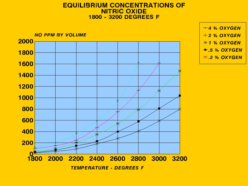
Water Vapour - H2O Carbon Dioxide - CO2 Sulphur Dioxide - SO2, SO3 Carbon Monoxide - CO Unburned Hydrocarbons - UBC Nitrogen Oxides - NO, NO2

36
Flame Speed Another important factor in Combustion is the Flame Speed
Each gas burns in air at a particular speed under reference conditions A stable flame is produced when the Flame Speed and gas/air mixture velocity correspond

37
Typical Flame Speeds (ft/sec)
Methane 1.48 Ethane 2.30 Propane 2.78 Butane 2.85 Hydrogen 9.30 Carbon Monoxide 1.70

38
Other Gas Characteristics
All fuel gases will burn within a mixture range both below Stoichiometric and above Stoichiometric. The “flammability range” varies between gases, and is another indicator of how easily a gas will burn. Gas density affects burner design as heavier gases have higher pressure drops though gas jets.

39
So why have burners?

40
Basic Objects of a Burner
The burner must mix the fuel and the air effectively to ensure complete combustion. The flame must be stabilised in a fixed position so that its heat can be absorbed effectively. The flame shape must be controlled to suit its working environment.

41
Process Heater Burners

42
Basic Burner Types Natural Draught
Premix Raw Gas (Nozzle Mix) Combination Oil & Gas
 Combination Oil & Gas.")
43
Natural Draught Air is pulled through the burner by draft created by the heat in the furnace and stack (explained in a later section). Since air velocity is low we need to use the energy in the gas (typically at 1 barg) to improve the gas/air mixing. We have 2 basic ways we do this.
 to improve the gas/air mixing. We have 2 basic ways we do this.")
44
Premix Burners Fuel pressure drop occurs in the gas jet.
Gas velocity in venturi induces part of the air so air flow adjusts with gas flow. Fuel and primary air mix before the nozzle. Secondary air mixes in burner throat. All domestic gas burners are premix, including cooking appliances.

45
Basic Burner Types Pre-Mix Heater Burner
GAS NOZZLE

46
Pre-Mix Burner Advantages
Large fuel gas discharge orifice. Large ports in firing nozzle. Small flame volume. Automatic variation of air flow with varying fuel rates.

47
Premix Burner Disadvantages
Can only accept small variations in gas quality without adjustment (n.b. unless Wobbe Index is maintained) Limited turndown. Difficult to adapt for combination gas/oil firing (but not impossible) Maintenance more difficult. Hard to reduce NOx.
 Limited turndown. Difficult to adapt for combination gas/oil firing (but not impossible) Maintenance more difficult. Hard to reduce NOx.")
48
Raw Gas Burners (Nozzle Mix)
Gas and air are kept separate until discharged into the combustion zone. Fuel pressure drop occurs at the combustion zone. The energy in the gas helps mix fuel and air.

49
Basic Burner Types Nozzle Mixing Gas Burner
GAS NOZZLE BURNER THROAT FLAME HOLDER

50
Basic Burner Types Raw Gas

51
Zeeco Burner for United

53
Test Burner Flame

54
Nozzle Mixing Gas Burner Advantages
A high turndown ratio No possibility of flashback The ability to burn a wide variety of fuels with differing heating values Flame shape can be controlled as required by gas tip and tile design. Can be adapted many ways to reduce NOx

55
Nozzle Mixing Gas Burner Disadvantages
Small fuel discharge ports "Large" flame volume Fuel/air ratio is dependent on operators

56
Raw Gas Combination Designed to burn gas and fuel oil either separately or together. Inner tile stabilizes oil flame with controlled primary air. Gas burners stabilize in secondary tile throat. Oil guns remove easily for cleaning while gas burners are in service. Gas burners can also be maintained while oil burners are in service.

57
Combination Natural Draught Gas and Oil Burner
PRIMARY TILE GAS TIPS

58
Combination Burner Limitations
Oil guns need frequent maintenance. Oil firing problems can cause fouling of gas tips. Total capacity of burner is set by air flow available, so firing gas and oil at the same time requires both fuels to be limited to give correct total Heat Flow.

59
Forced Draught Burners
Basically similar to Natural Draught Raw Gas Burners (including Combination Oil/Gas Burners). Higher air velocities give better mixing and smaller flames. Air can be preheated, using various types of heat exchanger. Flames are hotter, giving higher rates of heat transfer.
. Higher air velocities give better mixing and smaller flames. Air can be preheated, using various types of heat exchanger. Flames are hotter, giving higher rates of heat transfer.")
60
Gas pilots Most process burners use a pilot to provide the basic source of ignition. Pilot is usually fully premixed. Pilot can be ignited manually or have a built-in spark ignition. Some pilots have flame rods to check flame is alight.

61
Pilot Burner

62
Burners are only part of the system

63
Furnaces A furnace is basically an insulated box lined with tubes containing the process fluid. We fire burners inside the box to heat the tubes by a mixture of radiation and convection heat transfer. There are many different furnace designs depending on the process application and the companies involved. The next 2 slides show some basic types.

64
Heater Types

65
Heater Types

66
Heater Parts

67
Burner Locations Depending on the heater layout burners may be installed up-fired, side-fired, end-fired and down-fired. Most heaters are up-fired, except for special types such as Ethylene Crackers and Reformers.

68
Heat Transfer (a) - Radiation
In the firebox we get heat transferred initially by direct radiation from the flames to the tubes. Additional heat is radiated to the back of the tubes from the hot furnace walls. Radiant efficiency depends on the emissivity of the flame and of the tube surfaces, plus the temperatures of both.

69
Heat Transfer (b) - Convection
Hot gases passing over tube surfaces heat the tubes mainly by Convection. Away from the Flames most heat is transferred by Convection. A Convection Bank is a section of the Heater where Radiation is insignificant, normally just below the Stack.

70
Process Flow In most heaters the coolest fluid is exposed to the coolest heat source. Fluid passes first through the Convection Tubes, where available. Fluid exits near the burners.

71
Furnace Draught Natural Draught burners depend on the air flow being created by the difference in air pressure between the inside of the heater and outside. The reason the pressure is different is that the air inside the heater is hotter than the air outside. Since hot air is lighter it rises and reduces the pressure inside the heater.

72
Furnace Draught Typically the temperature in a firebox is 500 - 800°C.
At this temperature the draft increases by about 2.5 mm water for every 3 metres of firebox height. If we have a convection section we need more draught above it to overcome the pressure drop through the tube bank.

73
Where Draught comes from
10ft column of air at 1000degF = 0.05”w.g. 10ft column of cold air = 0.15“w.g. DRAUGHT = 0.1” /2.5 m.m.

74
Furnace Draught The temperature in the stack is lower, so we need more stack height to give us the required draught. The next chart shows what happens in our heater with a convection bank and a stack damper

76
More on Draught We need just enough air to burn our fuel properly.
We do not want any air to get in except through the burners. Any air which does not pass through the burners just absorbs some of the heat available and throws it away up the stack.

77
Even more on Draught We need to keep draught negative all the way through the heater. If we get a positive draught then hot gases will find small holes and make them bigger. The critical point is usually at the top of the firebox – look at the chart again. Many heaters have alarms for positive pressure.

78
Smallest Draught

79
Heater Tuning

80
Before Tuning Before tuning make a full check of the burner conditions. Ensure air doors are open equally and gas valves open completely. Check flame appearance / stability. Close all peep doors. Keep in Radio touch with panel operators.

81
Heater Tuning Draught Calculation / Setting
For a typical heater as in the sketch we should have about 2 mm draught at the arch. If the heater is 10 metres high we can expect an additional 8-9 mm at the floor This gives us 12 mm total. Burners should have been designed for slightly less than this theoretical draught, so we close the air doors to control the excess air through the burners. After we close the air doors we may need to adjust the stack damper to maintain 2 mm at the arch. We check O2 and draught and repeat adjustments until we get both figures correct.

82
HEATER ADJUSTMENT FLOW CHART
TARGET DRAFT 1 to 3 mm water TARGET OXYGEN 2 – 3 % START CHECK DRAFT HIGH LOW CHECK O2 CHECK O2 TARGET HIGH LOW HIGH LOW CLOSE STACK DAMPER OPEN AIR REGISTERS CLOSE AIR REGISTERS OPEN STACK DAMPER RETURN TO START RETURN TO START CHECK O2 HIGH LOW ON TARGET CLOSE AIR REGISTERS OPEN AIR REGISTERS RETURN TO START RETURN TO START GOOD OPERATION

83
HEATER ADJUSTMENT FLOW CHART
TARGET DRAFT 1 to 3 mm water TARGET OXYGEN 2 – 3 % START CHECK DRAFT TARGET CHECK O2 HIGH LOW ON TARGET CLOSE AIR REGISTERS OPEN AIR REGISTERS RETURN TO START RETURN TO START GOOD OPERATION

84
Heater Tuning Draught Control – General
There are differences in approach depending on the type of burner, if the heater has a convection bank, and if there is a stack damper. If the burners are in a plenum and have their own air doors then we have an extra adjustment point. In such cases the individual burner air doors should be fixed open unless a burner is stopped, when they should be shut. Sinclair has almost every combination possible, so we have to look at all the possibilities.

85
Heater Tuning Draught Control – Raw Gas Burners
Basically the Flowchart given applies to this type of burner. If there is no stack damper we need to monitor the arch Oxygen – assuming that the furnace leaks have been fixed. We must still check that Draught is negative as putting too much air through burners can cause draft to go positive at the arch.

86
Heater Start-up During start-up draught is low as temperatures are low. Pilots self-inspirate so should work normally. High excess air is used to control furnace temperature rise. Individual Burner light-off should be done with air doors nearly closed, so gas lights more smoothly. Increase air opening slowly so burner heats up quickly and flame can stabilize properly.

87
Heater Tuning Fuel Gas Valves
Valves fitted upstream of each burner are for isolation only. The only time a valve should not be opened fully is during light-off. If any valves are not completely open then the burners are not all firing at the same rate. Gas pressure trip settings are established on the basis that valves are fully open. If a trip setting interferes during normal operation it should be checked and may be changed, provided that the burner stability is checked at the revised setting. If an individual burner gives a problem with the valve open then the problem should be investigated. On many burners there are small gas jets which can plug easily and will affect flame stability.

88
What can go Wrong? O2 falls too low – Temperature control is lost as fuel does not burn – flames search for air and blow back through registers – “Puffing” – CUT BACK ON FUEL FIRST Draught goes positive – gas leaks out of any gaps and causes damage, but O2 still looks OK. Heaters should have an alarm for high pressure.

89
Heater Tuning Flue Gas Analysis
In general a good target for excess Oxygen is 3% We need this level in the firebox – that should mean we are getting the right amount of air through the burners. Gas samples taken above convection banks include any air which leaks in around the tubes. These leaks should always be minimised as they affect the convection bank efficiency. In serious cases the leaks can exceed our 3% target, so we could actually be firing below stoichiometric.

90
Heater Tuning Flue Gas Analysis
One way to check what is really happening is to also measure CO levels. Typically it is safe to run with a maximum of 50 ppm of CO in flue gases. Older burners will start producing CO at around 2% excess Oxygen, so we have a good indication of the actual excess air through the burners. On-line CO analysers allow burners to be run safely right down to their minimum achievable levels of excess air.

91
Heater Tuning Summary We are aiming to have 3% excess oxygen in the firebox. We need all the burners in each heater to be operating with the same amount of fuel and air. This means air doors set equally, gas valves full open, and clean gas tips. If there is a stack damper, it should normally be set to give a draft of 0.1” maximum at the heater arch. Some heaters may still need more draft to get enough air through the burners.

92
Nitrogen Oxides (NOx) Formation
 Formation")
93
What is the Problem? All combustion processes produce some Nitrogen Oxides In the atmosphere these oxides can form Nitric acid and fall as acid rain They react with other gases and sunlight, producing ozone and smog

94
NOx Formation in Combustion
In ambient conditions Nitrogen is an inert gas

95
NOx Formation in Combustion
In hot flames we get Thermal NOx Fuel NOx

96
Thermal NOx Created from atmospheric Nitrogen
Formation controlled by the breaking of N2 molecules to reactive nitrogen atoms by the supply of heat. The N atoms then react with available Oxygen to form NO. Thermal NOx formation rate is dependent on peak flame temperature and oxygen availability.

97
Controlling Reactions Thermal NOx

98
NOx definitions The primary component formed in a flame is NO.
In the atmosphere this NO converts to NO2, which is the harmful form. We define limits as NOx, where all measured levels are treated as having converted to NO2. Fired Heater limits are always expressed as the equivalent levels of NOx at 3% excess Oxygen. EPA bases limits on lbs/million Btu rather than on percentages.

100
Fuel NOx Some fuels contain ‘fixed’ Nitrogen as compounds. Liquids and Solids contain more of these than most gases. These compounds break down in the combustion process and release the Nitrogen in a form which reacts easily to form NOx. Nitrogen as a gas component is not significant. NOx levels increase in direct proportion to the fixed Nitrogen in the fuel. NOx reduction techniques are also effective in reducing Fuel NOx.

101
How can we reduce NOx? Reduce the Flame Temperature
Reduce the Oxygen available Flue Gas Treatment

102
Reducing Flame Temperature
Slow down fuel / air mixing Inject cooler inert gases into the flame (steam or recycled flue gas) Increase the excess air Reduce air below stoichiometric Unfortunately all of these things conflict with our requirement to get maximum heat from the flames to the process
 Increase the excess air. Reduce air below stoichiometric. Unfortunately all of these things conflict with our requirement to get maximum heat from the flames to the process.")
103
Reducing Available Oxygen
Reduce the excess air Inject Inert gases into the flame to reduce the oxygen concentration available (recycled flue gas again)
")
105
Low NOx Burners Staged Air Staged Fuel Low NOx
Internal Flue Gas Recirculation Combination of Features

106
Staged Air Burner Features
Sub-Stoichiometric Primary Combustion Presence of CO and H2 Flame Cooling in Second Stage Works with Gas or Oil

107
Staged Air Burner

108
Staged Air Burners Disadvantages
Long Flames Complicated Air Adjustment Fuel Composition affects Performance Higher Excess Air Required Limited NOx Reduction

109
Staged Fuel Low NOx Burners
Features / Advantages Disadvantages

110
Staged Fuel Burner Features
Two Stage Fuel Injection Good Heat Transfer from Secondary Flame Combustion Product Injection "Compact Flame“ Tolerates gas variations

111
1. Two stage fuel injection
Primary gas burns with high excess air, cooling the flame Secondary gas mixes into flame above the burner, where oxygen level is low, so burns at a lower temperature

112
2. Heat Transfer from Secondary Flame
Secondary Flame burns slowly above the burner Maintains uniform radiant Heat transfer further up the furnace

113
3. Combustion Product Injection
Secondary gas pokers are above the burner tile They induce furnace gases into the Secondary flame Oxygen is reduced but temperature increases, maintaining flame dimensions well

114
4. Compact Flame High excess air primary flame gives strong core to flame Controlled secondary mixing and recirculation keeps flame relatively compact

115
5. Tolerates Gas variations
Balance of primary to secondary gas is fixed (typically 30-40% primary) Stoichiometry is not affected by fuel properties
 Stoichiometry is not affected by fuel properties.")
116
Staged Fuel Burner

119
Staged Fuel Burner Disadvantages
Turndown is limited Stability sometimes a problem Small Gas Port Size Effectiveness of NOx reduction depends on fuel properties

120
Combination of Staged Fuel and Internal Flue Gas Recirculation
Low Emission Burners Combination of Staged Fuel and Internal Flue Gas Recirculation

121
Low Emission Burner Based on Staged Fuel Burner
Primary Gas induces furnace gases into Primary Flame “Zoning” of air in burner throat gives high stability Self compensates for gas changes

122
Internal Flue Gas Recirculation
Recycle Gas Flue Gas Burner Recycle Gas Furnace

123
Flue Gas Recirculation
Hot flue gases rise fast up the centre of the furnace Cooler gases travel down wall around tubes to the floor Gases have only Excess Oxygen and relatively low temperature Lighter fuel gases run at higher pressure / velocity, maintaining recirculation levels

124
Flame Retention Primary gas induces ‘inert’ gas into the burner throat. Flame holder mixes limited air with fuel and recirculated gases to give a fuel-rich zone around the outside of the flame holder for high stability Balance of air passes through centre of flame holder to mix into the primary flame

125
Staged Fuel Staged fuel induces more inert gases into flame
Mixing is delayed by the fuel-rich zone on the outside of the primary flame

126
Internal Flue Gas Recirculation Burner

127
Relative Process Heater Burner NOx Levels for Conventional and Low NOx Burners
Conventional # NOx/MMBtu, 100 ppmv Staged Fuel # NOx/MMBtu, 50 ppmv Low Emission # NOx/MMBtu, 25 ppmv

128
Boustead International Heaters.
END

Similar presentations


 Chapter 12 Page 147-168. NO x emissions include: Nitric oxide, NO, and Nitrogen dioxide, NO 2, are normally categorized as NO.>")

 van Leeuwen.>")


