Download presentation
Presentation is loading. Please wait.

1
ELC 119R-S Electrical Safety Refresher for Subcontract Electrical Workers

2
Outline Introduction Shock and Arc Flash
2 Electrical Hazard Mitigation 3 Technical work documentation (TWD) 4 Safe switching procedures 5 Wrap-Up
 4 Safe switching procedures. 5 Wrap-Up.")
3
Introduction ~ 300 workplace electrocutions annually
Estimated 20,000 shocks for every electrocution ~ 4000 injuries annually requiring days away ~3600 disabling electrical contact injuries annually 10-15 workers hospitalized daily with electrical burns 4-year average of 23 electrical events at SNL

4
Most Common Electrical Events at SNL
Short circuit of energized parts to ground Workers shocked from approaching nearer than a safe distance from exposed live parts Workers shocked from faulty equipment Workers shocked from plugging/unplugging equipment

5
Module 1: Shock and Arc Flash
The passage of electric current through the body from contact with an electric circuit (conductors). Exposure to electrical energy may result in no injury at all or may result in devastating damage or death. Electrocution is death by electrical energy resulting from the passing of a high magnitude electric current through the body 5
. Exposure to electrical energy may result in no injury. at all or may result in devastating damage or death. Electrocution is death by electrical energy resulting. from the passing of a high magnitude electric current. through the body. 5.")
6
Why Are We Susceptible to Injury by Electric Shock?
Our highly developed nervous system makes us extremely sensitive to even very small electric currents. The passage of current through the body results in heating of tissue Each of these interactions has serious consequences. 6

7
Effects of Current on the Body
Current Value Effects < 1 ma Barely Perceptible 1-5 ma Perceptible shock, reflex actions 5 ma GFCI trips Accepted as maximum harmless current 6-10 ma Painful shock, victim can “let-go” 10-20 ma Painful shock, victim can not let go ma Ventricular Fibrillation possible ma Ventricular Fibrillation likely 200 ma Severe burns, severe muscular contractions, chest muscles clamp the heart and stop it for the duration of the shock. 833 ma Current used by 100 watt light bulb

8
Effect of Current Passing Through the Body
Current can confuse or damage nerve control centers of lungs and heart Heat damage caused by dissipation of energy- body acts as a resistor.

10
Unfortunate mouse suffers a fatal phase to phase shock

11
Factors Affecting Shock Remember Ohm’s Law: E=IR
Current: most important factor, though directly determined by voltage and body resistance. Path of current: greater chance for survival if current passes through extremities only Duration of Shock: according to IEEE std. 80, the maximum safe duration can be determined by using: t (seconds) = .116/(V/R)
 = .116/(V/R)")
12
Example If an electrician gets a shock from a 277 volt light fixture, would he/she get “stuck” on the circuit? Let’s assume the worker was sweating and use a resistance value of 10,000 ohms. I =E/R I = 277/10,000 I = amps or ~28 ma

13
YES! Is He/She Stuck? Current Value Effects <1 ma
Barely Perceptible 1-5 ma Perceptible shock, reflex actions 5 ma GFCI trips Accepted as maximum harmless current 6-10 ma Painful shock, victim can “let-go” 10-20 ma Painful shock, victim can not let go ma Ventricular Fibrillation likely ma Ventricular Fibrillation occurs 200 ma Severe burns, severe muscular contractions, chest muscles clamp the heart and stop it for the duration of the shock. 833 ma Current used by 100 watt light bulb YES!

14
Example continued Let’s also assume that the path of the current is hand to hand. How long does this person have before the shock could be considered fatal? T = .116/(V/R) T = .116/(277/10,000) T = .116/.0277 T = 4.18 seconds!
 T = .116/(277/10,000) T = .116/.0277 T = 4.18 seconds!")
15
Voltage Thresholds OSHA set threshold for hazardous energy at 50 volts
Hazard from applications lower than 50 are usually thermal not shock: batteries, super capacitors, etc. At levels greater than 600 V, skin is usually penetrated driving resistance down.

16
Entry and exit wounds

17
Rescuing and Treatment
Step 1 – Check to see that the area is safe to enter Step 2 - Call 911 immediately Step 3- Rescue the victim with an insulated device (hot stick, rope, dry wood, etc) Step 4 – Begin CPR Step 5 - Continue resuscitation Step 6 - Get medical attention for the victim
 Step 4 – Begin CPR. Step 5 - Continue resuscitation. Step 6 - Get medical attention for the victim.")
18
II Arc Flash A release of thermal energy from an electric arc by the vaporization and ionization of materials, reaching temperatures up to 35,000 °F. Exposure to these extreme temperatures both burns the skin directly and causes ignition of clothing. (2004 NFPA 70E)
")
19
Nature of the Arc Arc results from passing of current through air
Terminals vaporize and serve as conductive medium for ionized gasses Flash can extend further than 10’ from the source Pressure wave caused by rapid expansion of gases with flying molten materials and shrapnel The blast can destroy structures, and knock workers from ladders or across a room. The blast can rupture eardrums and collapse lungs.

20
Nature of the Arc continued

21
Three Factors Affecting Arc Energy
Available short circuit current Duration of the arc Distance from the arc

22
Burns From the Arc First degree: surface only. Skin is usually red and tender Second degree: blistering of the skin. Most painful Third degree: complete destruction of the skin with charring of tissue. Most dangerous –susceptible to infection. Skin can not heal itself.

23
First Degree Burns from a 480 Fault

24
Second Degree Burns from the same 480 Fault

25
Effects of the Arc- Burns
Arcs have ignited clothing 10’ from the arc and can be fatal when within a few feet

26
Accelerator Flash Incident
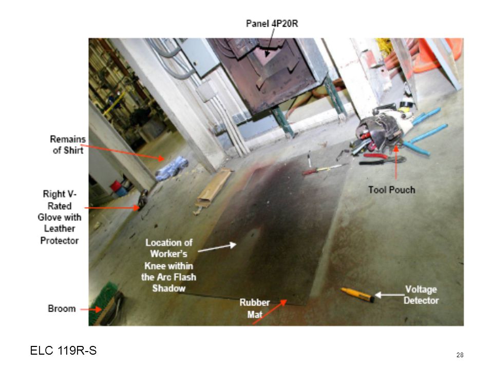
On October 11, 2004, at approximately 11:15 am, a subcontractor electrician working at an Accelerator Center received serious burn injuries requiring hospitalization due to an electrical arc flash that occurred during the installation of a circuit breaker in an energized 480-Volt (V) electrical panel.
 electrical panel.")
27
Arc flash 2004

30
Importance of FR Clothing 60/40 blend here

31
From the Type A Investigation…
Description of Injuries: Electrician received third degree burns on the face, chest, and legs and second degree burns on the arms, involving approximately 50% of his body. Because of the seriousness of his condition, the Board was not able to interview him.

32
Module 2: Electrical Hazard Mitigation
Plan your work Analyze/identify the hazards Control the hazards Perform the work Improve the process for the next operation

33
1910 CFR 851 and NFPA 70E All Department of Energy Facilities are contractually required by law follow 10 CFR 851- Worker Safety and Health Protection Plan 851.23(a)(14) requires contractors to comply with NFPA 70E as a baseline. 70E is the industry standard for addressing electrical hazards in the workplace Applying 70E standards nothing more than using integrated safety management
(14) requires contractors to comply with NFPA 70E as a baseline. 70E is the industry standard for addressing electrical hazards in the workplace. Applying 70E standards nothing more than using integrated safety management.")
34
TURN IT OFF! Energized work no longer allowed at SNL unless:
“de-energizing introduces additional or increased hazards or is infeasible due to equipment design or operational limitations” 70E A.1 Most hazards can be controlled by insulating, guarding, or by simply working de-energized

35
Electrically Safe Work Condition
First priority is to de-energize Review safety plan Inspect equipment, disconnect energy sources, and lock and tag energy sources. Post barricades and signs to establish the limited approach and flash protection boundaries. Open enclosure, identify shorting devices, and discharge energy-storage devices if applicable. Perform Zero Energy verification Test Complete work When the work is completed, test circuits, remove tools, and test gear, perform final check, and close enclosure NOTE: Equipment is not considered de-energized until locked out and verified

36
Energized Work - provided justification requirements (slide 34) are met
Strict requirements addressing worker qualifications: Qualified Person: One who has the skills and knowledge related to the construction and operation of the electrical equipment and installations and has received safety training on the hazards involved (Electrical Safety in the Workplace, 2004). Energized work must be authorized by Senior Manager Facilities Engineering- see your contract Sandia delegated representative (SDR) Shock and Flash Hazard Analyses required. This can be accomplished using the table on slide 44. Remember 2 different hazards- shock and flash
. Energized work must be authorized by Senior Manager Facilities Engineering- see your contract Sandia delegated representative (SDR) Shock and Flash Hazard Analyses required. This can be accomplished using the table on slide 44. Remember 2 different hazards- shock and flash.")
37
Shock Hazard Analysis Required ANYTIME a worker crosses the Limited Approach Boundary to exposed live parts Must determine approach boundaries (Limited and Restricted) and required shock PPE (usually gloves and insulated tools) Shock PPE required ANYTIME a worker crosses the Restricted Approach Boundary
 and required shock PPE (usually gloves and insulated tools) Shock PPE required ANYTIME a worker crosses the Restricted Approach Boundary.")
38
Shock Approach Boundaries
Limited Approach Boundary (LAB) Level II authorization required Only qualified workers may cross * Boundary must be physically established Restricted Approach Boundary (RAB) No unqualified workers Shock PPE required Shock PPE mainly consists of insulating gloves and tools Refer to slide 44 for LAB and RAB approach distances and required PPE.
 Level II authorization required. Only qualified workers may cross * Boundary must be physically established. Restricted Approach Boundary (RAB) No unqualified workers. Shock PPE required. Shock PPE mainly consists of insulating gloves and tools. Refer to slide 44 for LAB and RAB approach distances and required PPE.")
39
Flash Hazard Analysis Required ANYTIME a worker crosses the flash protection boundary (FPB) Must determine the Flash Protection Boundary and the PPE required for crossing this boundary PPE and distances determined from table slide 44

40
Arc Flash Protection PPE and flash protection boundary (FPB) in CSSP will match that of arc flash hazard (AFH) label on equipment If the electrical equipment is not provided with an AFH warning label, PPE and FPB in CSSP will be determined using the table in slide 44.

41
Exposed Live Part Limited Approach Boundary (shock)
Level II authorization required Only qualified workers may cross – unqualified workers may cross if escorted by qualified worker and made aware of the hazards Boundary must be physically established Flash Protection Boundary Distance and PPE determined from table in slide 42 PPE required of ANYONE inside this boundary Restricted Approach Boundary (shock) No unqualified workers Shock PPE required Shock PPE mainly consists of insulating gloves and tools
 No unqualified workers. Shock PPE required. Shock PPE mainly consists of insulating gloves and tools.")
42
Hazard Risk Categories (HRC)
HRC 0: Single phase circuits operating at volts HRC 1&2: Three-phase circuits operating between 120 and 600 volts HRC 3&4: Three-phase service entrance equipment and switchgear operating between 120 and 600 volts, excluding those systems with a RED, Level V Arc Flash Hazard label.

43
Hazard Risk Categories (HRC)
Hazard Risk Above Forty Calories: All equipment identified with a Level V (red) Arc Flash Hazard label Hazard Risk Greater Than 600 volts: Obtain flash hazard analysis. Exception: HRC 2 PPE shall be worn In 15 kV manholes. Head, face and glove protection may be removed during cable terminations if no other work is being performed in the manhole.
 Arc Flash Hazard label. Hazard Risk Greater Than 600 volts: Obtain flash hazard analysis. Exception: HRC 2 PPE shall be worn In 15 kV manholes. Head, face and glove protection may be removed during cable terminations if no other work is being performed in the manhole.")
44
Boundary and PPE Table Equipment Class HRC Flash Boundary LAB, RAB
Required flash PP Required shock PPE PPE Code 208/ ø 4’ 3’ – 6”, contact EWC Class 0 gloves with leather protectors and insulated tools Green 120/240, 277/480 3-ø non service entrance 1, 2 6’ 4’, 1’ EWC + accessories Blue 3-ø service entrance 3 Contact FMOC project lead ISC Yellow 4 ESC Orange Equipment labeled greater than 40 calories or 600 volts NA Contact SDR, CO, or PM for assistance Red EWC: FR long sleeve shirt (min arc rating = 8) worn over untreated cotton t-shirt with FR pants (min arc rating = 11, safety glasses Accessories: hard hat w/FR rated face shield, hearing protection, and leather boots or shoes IWC: EWC + accessories + FR coveralls (min arc rating = 25) and double –layer switching hood. ESC: 40-calorie switching suit w/rated hood and gloves, leather boots and shoes.
 worn over untreated cotton t-shirt with FR pants (min arc rating = 11, safety glasses. Accessories: hard hat w/FR rated face shield, hearing protection, and leather boots or shoes. IWC: EWC + accessories + FR coveralls (min arc rating = 25) and double –layer switching hood. ESC: 40-calorie switching suit w/rated hood and gloves, leather boots and shoes.")
45
Example Arc Flash Labels
Level I (HC-0) Label Level II (HC-1 and HC-2) Label
 Label Level II (HC-1 and HC-2) Label.")
46
Electro-Magnetic Energy
Whenever you have electric power, electric and magnetic fields will be generated. The electric field is often generated by the alternating voltage of the electrical system. The higher the voltage, the greater the electric field. Taken together, electric and magnetic fields are often referred to as electromagnetic radiation. The main effect of exposure to EME is heating of tissue and organs. There are rooftop antennas at Sandia that emit varying levels of EME so contact your ES&H coordinator before approaching them

47
Worker Responsibilities
Familiarize yourself with procedures and work plans- CSSP Be aware of your surroundings Obey all warnings signs and regulations Always use proper PPE (slide 44) Stop work if an unsafe and/or unexpected condition arises Consider ALL electrical equipment energized unless locked out and verified de-energized
 Stop work if an unsafe and/or unexpected condition arises. Consider ALL electrical equipment energized unless locked out and verified de-energized.")
48
Worker Responsibilities
Do NOT perform unjustified energized work Do not wear jewelry when performing energized work Report ALL accidents, regardless of severity to Safety Officer/Supervisor Immediately report to your supervisor, anyone known to be under the influence of drugs or alcohol Be aware of secondary hazards- beryllium, radiation, noise, etc Be responsible for your own safety!

49
Planning Your Work Planning is a key element in performing work safely and is the first step in the ISMS process. OSHA and 70E require a job briefing be held before any electrical work operation begins. All personnel involved in the job shall be briefed on the safety concerns, energy source controls and precautions regarding their assignments. Should work conditions change or unanticipated hazards appear, additional briefings should be held. Planning must be documented!

50
Planning Your Work continued
Consider ALL hazards When changing a ballast, what hazards are involved besides electricity and working from heights? Is there an asbestos issue? Is the fixture in an area known to have dangerous levels of Beryllium? How about radiation?

51
Planning Your Work continued
The meeting must cover the following questions: Do I thoroughly understand the job? Do I thoroughly understand my role in the job? Am I aware of all the hazards I may encounter? Am I knowledgeable of all the safety rules and required personal protective equipment that apply to the job?

52
Performing Your Work All circuits must be considered energized until LOTO’d and verified de-energized Several events at SNL have been the result of failure to verify de-energized Performance of the 0 energy verification still requires PPE and boundary establishment (slide 44) Do you have to do this hot? Physically establish the limited approach boundary (slide 44) Boundary must keep unqualified workers out of area Boundary must warn workers of the hazards inside the area
 Do you have to do this hot Physically establish the limited approach boundary (slide 44) Boundary must keep unqualified workers out of area. Boundary must warn workers of the hazards inside the area.")
53
Performing Your Work Wear the appropriate PPE
Shirt must be buttoned and sleeves rolled down Flash PPE is required when inside the flash protection boundary (slide 44) Crossing the restricted approach boundary requires gloves and insulated tools (slide 44) Maintain your gloves Are they out of testing date requirements? Use the right tools for the job Is you meter rated for the task? Several events at SNL have occurred due to use of an inappropriate meter Do not deviate from job plan. If work outside of scope is required stop and re-evaluate with all involved co-workers.
 Crossing the restricted approach boundary requires gloves and insulated tools (slide 44) Maintain your gloves. Are they out of testing date requirements Use the right tools for the job. Is you meter rated for the task Several events at SNL have occurred due to use of an inappropriate meter. Do not deviate from job plan. If work outside of scope is required stop and re-evaluate with all involved co-workers.")
54
Module 2 Conclusion Severe hazards associated with energized electrical work Energized work is now the exception- not the norm- Turn –it-off! NFPA 70E provides sound guidance for electrical safety in the workplace Applying the standard is basic ISMS- identify the hazard, control the hazard Remember there are two primary hazards (shock and flash) that must be analyzed and controlled independently
 that must be analyzed and controlled independently.")
55
Module 3: TWD Requirements
Q: What is considered energized work at SNL? A: Any activity inside the Limited Approach Boundary (LAB) Crossing the LAB for ANY reason must meet the 70E justification requirements of A.1 (slide 35) ALL energized work requires a technical work document Why? This should be your first question when asked to work energized.
 Crossing the LAB for ANY reason must meet the 70E justification requirements of A.1 (slide 35) ALL energized work requires a technical work document. Why This should be your first question when asked to work energized.")
56
Contract Specific Safety Plan (CSSP)
The CSSP is the required technical work document for all energized work at SNL performed by a facilities subcontractor The CSSP must incorporate the required energized work permit elements required in NFPA 70E 130.1B2

57
Content of the CSSP A description of the circuit/part to be worked on and its location Justification of why the work must be performed energized. Remember that some troubleshooting could be accomplished with an Ohm meter. A description of safe work practices to be employed (second person, safety watch, Barriers, etc) Results of the shock hazard analysis (voltage the employee(s) will be exposed to) – slide 44 Determination of shock approach boundaries (LAB, RAB, PAB) using table slide 44
 Results of the shock hazard analysis (voltage the employee(s) will be exposed to) – slide 44. Determination of shock approach boundaries (LAB, RAB, PAB) using table slide 44.")
58
Content of the CSSP continued
6. Results of the flash hazard analysis (determination of the Flash Protection Boundary and the caloric exposure based on table slide 44 7. The necessary personal protective equipment- shock and flash Means used to restrict access of unqualified personnel to the area (chains, flagging, signage, etc) Evidence of completion of a pre-job briefing including topics covered- checklist Energized work approvals (workers, Managers, Senior Managers)
 Evidence of completion of a pre-job briefing including topics covered- checklist. Energized work approvals (workers, Managers, Senior Managers)")
59
Insulated Tools Insulated tools, rated for the system voltage, are required when contacting any energized component. Insulated tools should be listed under # 3. Ground hooks shall also be listed here. If the insulated tool can prevent the user from crossing the restricted approach boundary and flash protection boundary, PPE will not be required (except safety glasses).
.")
60
Module 4 Safe Switching Procedures
Three hazards associated with switching breakers or disconnects Shock Explosion Arc flash/blast

61
Shock Rare when switching because cover should be in place.
Remember shock boundaries 30,000 non-fatal shocks each year in the workplace… 247 died from electrocution in 2006…down from 251 in 2005.

62
Breaker Explosion Counterfeit Products Improper Sizing
Sub-standard components No NRTL listing Improper Sizing Improperly rated for available fault current

63
Arc Flash

64
Operating Breakers and Disconnects
Use one hand when possible. For side-handled switches, stand as far away to the side as possible to operate the switch. For panel-mounted breakers, do not stand in front of the panel when operating the breaker. Do not expose unprotected portions of the body/face to the potential blast.

65
Review – Switching Operations
Disconnect Rating Required PPE (Hazard Category) Up to and including 60 amps (< 600 volts) HC 0 * >60 up to and including 200 amps (< 600 volts) HC 2 * > 200 amps (< 600 volts) and all > 600 volts Must be analyzed by a qualified person. Contact electrical safety for evaluation. Arc flash labels supersede this table reference slide 44 for specifics
 Up to and including 60 amps (< 600 volts) HC 0 * >60 up to and including 200 amps (< 600 volts) HC 2 * > 200 amps (< 600 volts) and all > 600 volts. Must be analyzed by a qualified person. Contact electrical safety for evaluation. Arc flash labels supersede this table. reference slide 44 for specifics.")
66
Module 4 Conclusion Switching can be hazardous Wear appropriate PPE
Obtain AIC and clearing times prior to switching Never switch breakers or disconnects under trip conditions - call facilities Never close a breaker or disconnect if uncomfortable Use Left hand rule to keep body away from disconnect when closing

67
Course Wrap-Up You seldom get a second chance with electricity
Most electrical accidents are caused by unseen or unanticipated hazards Take your time! Never deviate from procedures If circumstances or conditions change- STOP and re-evaluate Work on energized equipment is restricted at SNL Maintain tools, test equipment, and PPE Never rely on others for your safety

68
Thanks for Viewing Questions: Greg Kirsch at 845-9497
Mark McNellis at Marc Williams at

Similar presentations


>")


