Download presentation
Presentation is loading. Please wait.

1
Chapter 2 Fundamentals of the Mechanical Behavior of Materials
Fetweb.ju.edu.jo/staff/ie/mbarghash Chapter 2 Fundamentals of the Mechanical Behavior of Materials

2
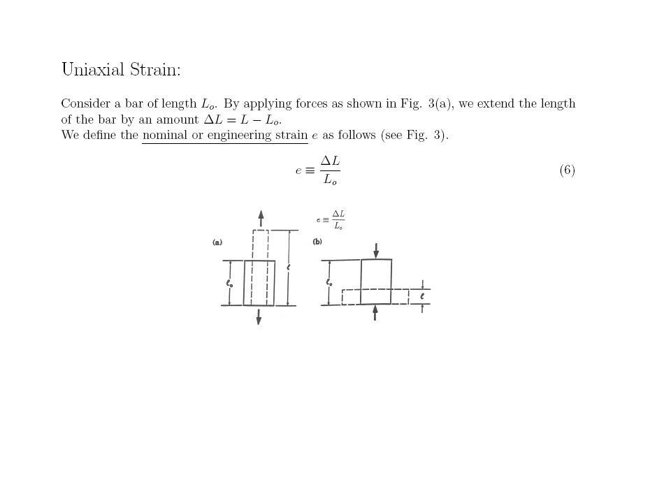
Types of Strain FIGURE Types of strain. (a) Tensile, (b) compressive, and (c) shear. All deformation processes in manufacturing involve strains of these types. Tensile strains are involved in stretching sheet metal to make car bodies, compressive strains in forging metals to make turbine disks, and shear strains in making holes by punching.
 Tensile, (b) compressive, and (c) shear. All deformation processes in manufacturing involve strains of these types. Tensile strains are involved in stretching sheet metal to make car bodies, compressive strains in forging metals to make turbine disks, and shear strains in making holes by punching.")
3
Universal testing machine

4
Tension Test Figure 2.2 (a) Original and final shape of a standard tensile-test specimen. (b) Outline of a tensile-test sequence showing stages in the elongation of the specimen.
 Original and final shape of a standard tensile-test specimen. (b) Outline of a tensile-test sequence showing stages in the elongation of the specimen.")
8
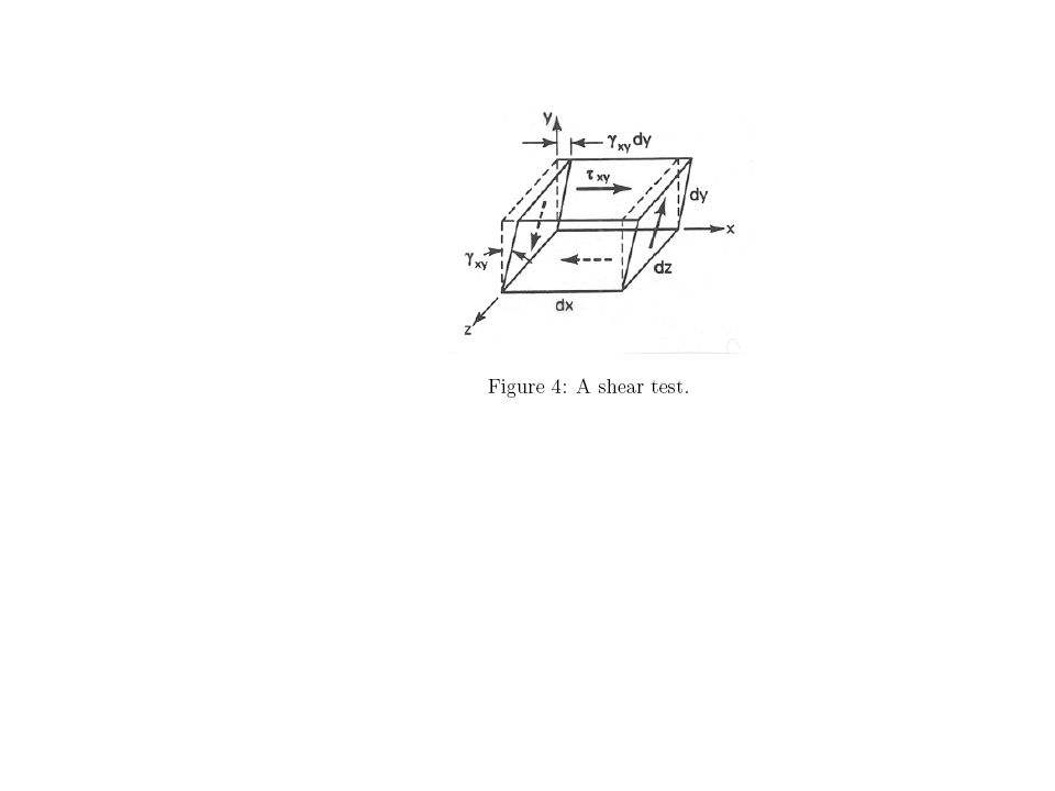
Understanding shear Not required Definition

9
Imperfections in engineering strain

11
First case ln(2Lo/Lo)=ln(2)
Second case ln(Lo/2Lo)=ln(1/2)=-ln(2)
=ln(1/2)=-ln(2)")
12
ln(2)=0.6931 ln(1.5)+ln(2/1.5)=0.6931
= ln(1.5)+ln(2/1.5)=0.6931")
16
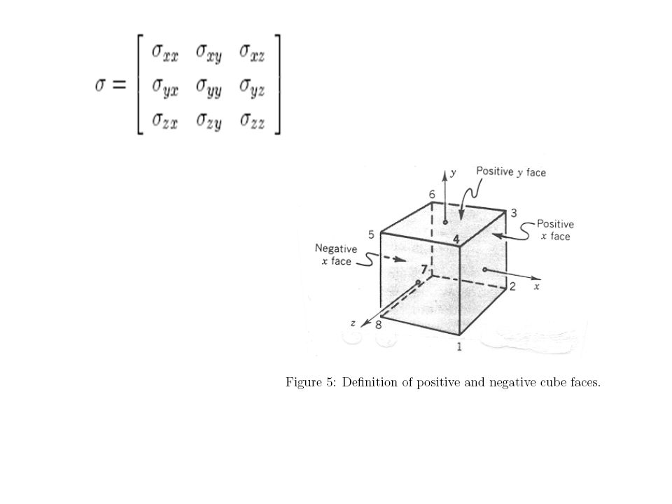
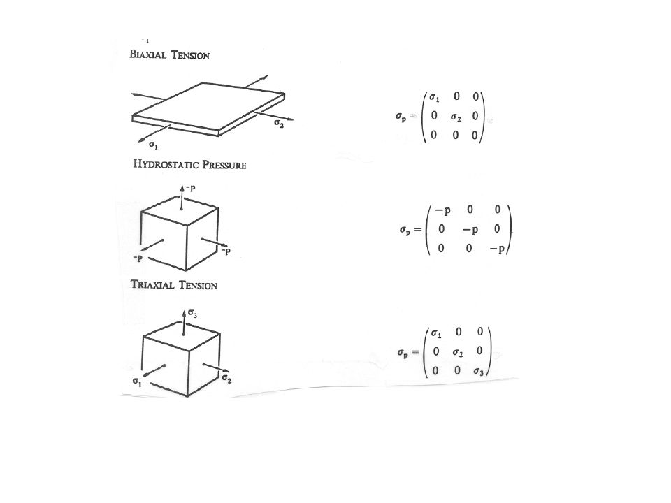
Stess in three dimensions
n is a vector, so tn is the stress on a plan with n as orthogonal to it

17
Special case n= x, There are other cases where n=y, n=z Thus we have 9 stress vectors

20
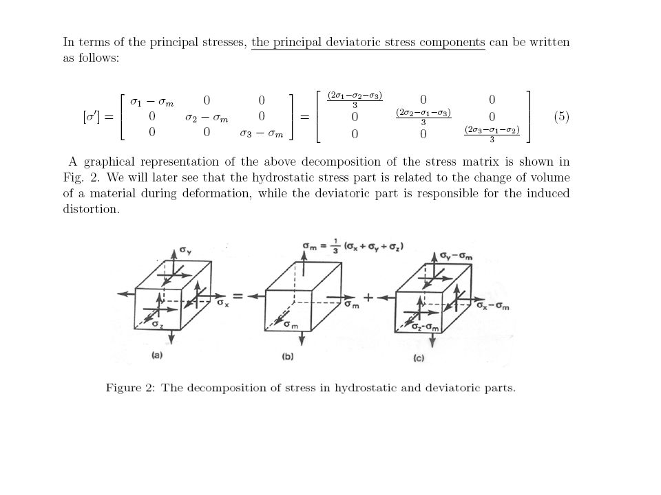
Hydraustaic and deviatoric stress

24
Homework: prove the above relation

26
The plastic deformation, the plastic deformation
Causes zero volume change Prove the above relation for A unit cube

29
Mechanical Properties of Materials
Table 2.1 Typical mechanical properties of various materials at room temperature.

30
Loading and Unloading FIGURE Schematic illustration of loading and unloading of a tensile-test specimen. Note that during unloading, the curve follows a path parallel to the original elastic slope.

31
True Stress-True-Strain Curves in Tension
FIGURE (a) True stress-true-strain curve in tension. Note that, unlike in an engineering stress-strain curve, the slope is always positive, and the slope decreases with increasing strain. Although stress and strain are proportional in the elastic range, the total curve can be approximated by the power expression shown. On this curve, Y is the yield stress and Yf is the flow stress. (b) True-stress true-strain curve plotted on a log-log scale. (c) True stress-true-strain curve in tension for 1100-O aluminum plotted on a log-log scale. Note the large difference in the slopes in the elastic and plastic ranges. Source: After R. M. Caddell and R. Sowerby.
 True stress-true-strain curve in tension. Note that, unlike in an engineering stress-strain curve, the slope is always positive, and the slope decreases with increasing strain. Although stress and strain are proportional in the elastic range, the total curve can be approximated by the power expression shown. On this curve, Y is the yield stress and Yf is the flow stress. (b) True-stress true-strain curve plotted on a log-log scale. (c) True stress-true-strain curve in tension for 1100-O aluminum plotted on a log-log scale. Note the large difference in the slopes in the elastic and plastic ranges. Source: After R. M. Caddell and R. Sowerby.")
32
Power Law Material Behavior
K: strength coefficient n: strain hardening coefficient Table 2.3 Typical values of K and n in Eq. (2.11) at room temperature.
 at room temperature.")
33
True Stress - True Strain Curves for Various Metals
FIGURE True-stress-true-strain curves in tension at room temperature for various metals. The point of intersection of each curve at the ordinate is the yield stress Y; thus, the elastic portions of the curves are not indicated. When the K and n values are determined from these curves, they may not agree with those given in Table 2.3, because of the different sources from which they were collected. Source: S. Kalpakjian.

34
Strain Rate Effects C: strength coefficient
Table 2.5 Approximate range of values for C and m in Eq. (2.16) for various annealed materials at true strains ranging from 0.2 to 1.0. C: strength coefficient M: strain rate sensitivity exponent
 for various annealed materials at true strains ranging from 0.2 to 1.0. C: strength coefficient. M: strain rate sensitivity exponent.")
35
Effect of temperature Power Law Creep
One of the most common forms of plastic flow is Power-Law Creep, given by the formula: Strain Rate = C (Stress)n exp(-Q/RT) Let's take each part of the formula in turn: C is a scaling constant. n means that the strain rate increases much faster than stress. Typically n is about 3 but can range from a bit less than 2 to 8. Recall that with viscous deformation stress is proportional to strain rate (n=1). With power-law creep it's faster: the effective viscosity drops with stress. Q is the activation energy required to get crystal dislocations moving. It's typically kilojoules per mole, sometimes up to 500. R is the Universal Gas Constant that turns up everywhere in physical chemistry. In SI units it equals joules/mole-degree Kelvin. T is the temperature in degrees Kelvin. As T increases, Q/RT decreases and thus exp(-Q/RT) increases, though much more slowly than exp(T). At very large T, Q/RT approaches zero and the exponential term approaches 1. This does not happen, though, at geologically realistic temperatures.
n exp(-Q/RT) Let s take each part of the formula in turn: C is a scaling constant. n means that the strain rate increases much faster than stress. Typically n is about 3 but can range from a bit less than 2 to 8. Recall that with viscous deformation stress is proportional to strain rate (n=1). With power-law creep it s faster: the effective viscosity drops with stress. Q is the activation energy required to get crystal dislocations moving. It s typically kilojoules per mole, sometimes up to 500. R is the Universal Gas Constant that turns up everywhere in physical chemistry. In SI units it equals joules/mole-degree Kelvin. T is the temperature in degrees Kelvin. As T increases, Q/RT decreases and thus exp(-Q/RT) increases, though much more slowly than exp(T). At very large T, Q/RT approaches zero and the exponential term approaches 1. This does not happen, though, at geologically realistic temperatures.")
36
Barreling In Compression
Plane Strain Compression FIGURE Barreling in compression of a round solid cylindrical specimen (7075-O aluminum) between flat dies. Barreling is caused by interfaces, which retards the free flow of the material. See also Figs. 6.1 and 6.2. Source: K. M. Kulkarni and S. Kalpakjian. FIGURE Schematic illustration of the plane-strain compression test. The dimensional relationships shown should by satisfied for this test to be useful and reproducible. This test give the yield stress of the material in plane strain, Y’. Source: After A. Nadai and H. Ford.
 between flat dies. Barreling is caused by interfaces, which retards the free flow of the material. See also Figs. 6.1 and 6.2. Source: K. M. Kulkarni and S. Kalpakjian. FIGURE 2.16 Schematic illustration of the plane-strain compression test. The dimensional relationships shown should by satisfied for this test to be useful and reproducible. This test give the yield stress of the material in plane strain, Y’. Source: After A. Nadai and H. Ford.")
42
Toughness It is the Area under the stress strain curve

44
Derive the instability point for plain stress case with equal stresses

45
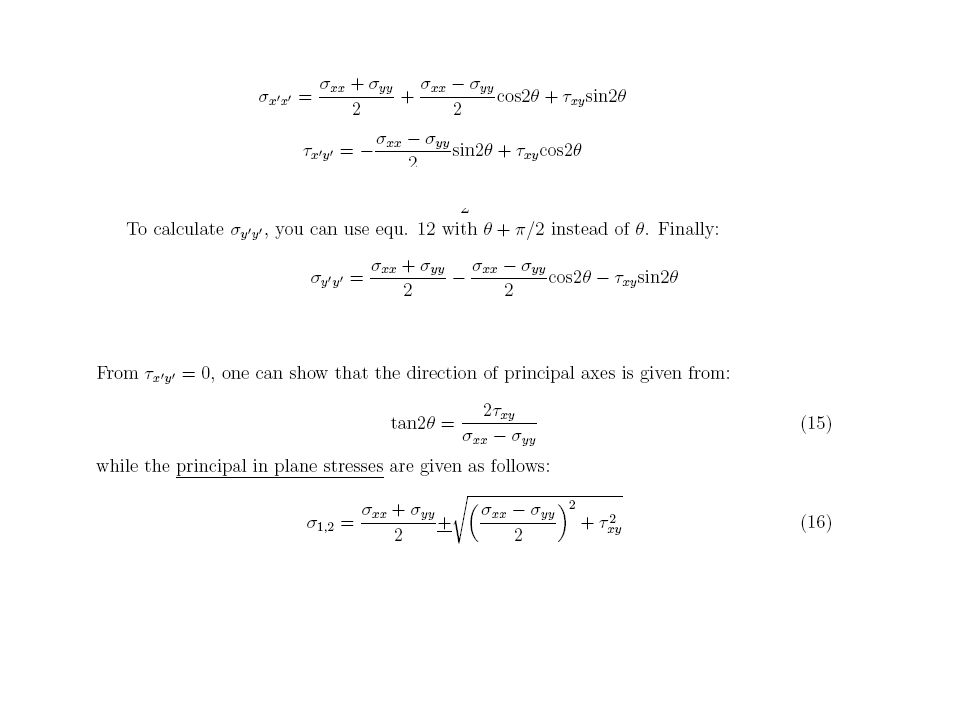
Principle stresses Since x, y, z are optional coordinates, then we can obtain Certain coordinates where the shear stresses disappear Example, the normal directions in simple tension

47
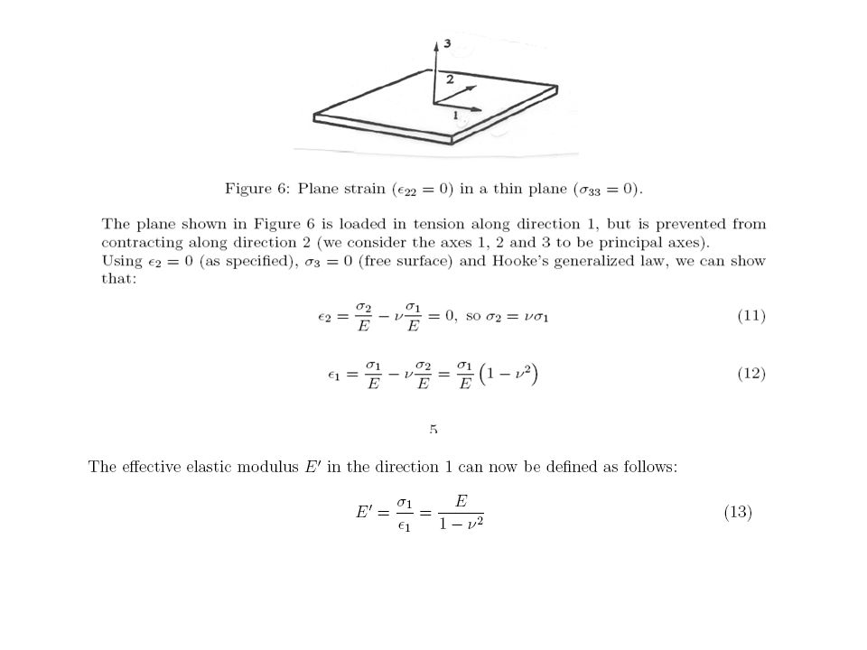
Two dimensional-plain stress case

52
Homework, (don’t submitted it, just solve it)
Find the maximum stress case for the simple tension And Find the principle stresses for the simple shear case

54
Not required

58
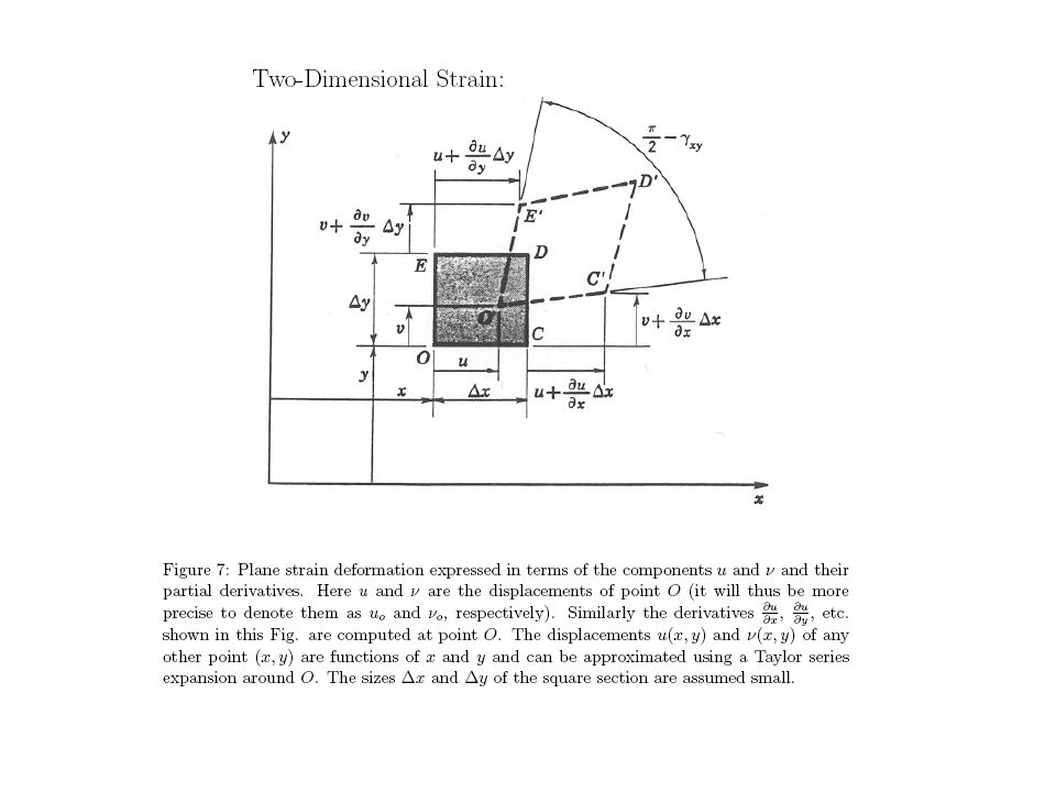
Plain strain transformation

59
Not required

66
Plane Strain A state of plane strain exits when the strains are confined to a single plane, such as the x-y plane. This generally means that the stresses in the other direction; eg., the z direction, are non-zero. Plane Strain occurs in thick sections that “constrain” out of plane deformations

67
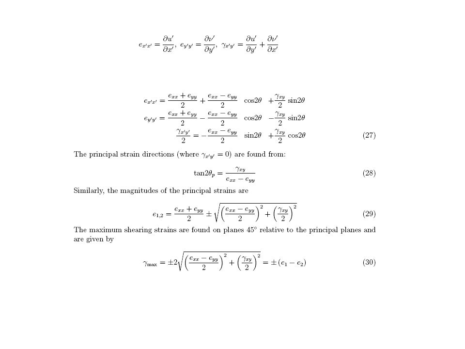
Transformations in plane strain
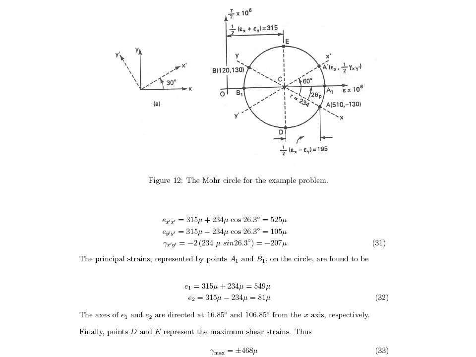
, e , g The state of plane strain at a point p is given by . Determine the x y xy principal strains and the maximum in-plane shear strain and show the orientations of the elements subjected to these strains. Also determine the absolute maximum shear strain. e =

68
g xy tan 2 q p e e x y Solution g 1 xy 1 -0.006 . . q atan atan p
( ) 2 e e 2 x y
 2. e. e. 2. x. y.")
69
Principal Strains -0.006 0.004 0.002 -79.6º -79.6º =0.005162
e e e e g x y x y xy . . . . e ' cos 2 q sin 2 q x p p 2 2 2 e e e e g x y x y xy . . . . e ' cos 2 q sin 2 q y p p 2 2 2 -0.006 0.004 0.002 . -79.6º e ' cos -79.6º sin x 2 2 2 = e’y=

70
Maximum Shear Strain = gmax = 0.006325
' e ' x y = g e ' test x e ' y gmax = Use diameters of circles!, Mohr’s circle plots g/2, so g is the diameter (=2x radius).
.")
71
Max In-Plane Shear Strain
=9.2º =

72
Mohr’s Circle Plot normal strain on the x-axis
Plot ½ the shear strain on the y-axis Solve as you would for plane stress problem g/2 e

73
Strain energy For the elastic region For 3D case For principle stress case

74
Plane Strain A state of plane strain exits when the strains are confined to a single plane, such as the x-y plane. This generally means that the stresses in the other direction; eg., the z direction, are non-zero. Plane Strain occurs in thick sections that “constrain” out of plane deformations

75
Transformations in plane strain
, e , g The state of plane strain at a point p is given by . Determine the x y xy principal strains and the maximum in-plane shear strain and show the orientations of the elements subjected to these strains. Also determine the absolute maximum shear strain. e =

76
g xy tan 2 q p e e x y Solution g 1 xy 1 -0.006 . . q atan atan p
( ) 2 e e 2 x y
 2. e. e. 2. x. y.")
77
Principal Strains -0.006 0.004 0.002 -79.6º -79.6º =0.005162
e e e e g x y x y xy . . . . e ' cos 2 q sin 2 q x p p 2 2 2 e e e e g x y x y xy . . . . e ' cos 2 q sin 2 q y p p 2 2 2 -0.006 0.004 0.002 . -79.6º e ' cos -79.6º sin x 2 2 2 = e’y=

78
Maximum Shear Strain = gmax = 0.006325
' e ' x y = g e ' test x e ' y gmax = Use diameters of circles!, Mohr’s circle plots g/2, so g is the diameter (=2x radius).
.")
79
Max In-Plane Shear Strain
=9.2º =

80
Mohr’s Circle Plot normal strain on the x-axis
Plot ½ the shear strain on the y-axis Solve as you would for plane stress problem g/2 e

82
*Prove the above relations
*prove that equation 21 and 22 are the same (for the plain stress case)
")
83
Principle stresses in three direction

84
We want to determine the normal and shear stresses on the plane
We want to determine the normal and shear stresses on the plane. The normal stresses are easiest. Unfortunately, we can't add stresses, only forces, so we have to determine the forces the stresses exert, add them up, then convert back to stress. Consider stress S1. It acts along the X1 axis, .but the stress "sees" only the area of the plane visible along the X1 axis, which is c1. So F1 = S1c1. Similarly, F2 = S2c2 and F3 = S3c3. The force normal to the plane exerted by F1 is F1c1, and the total force normal to the plane is F1c1 + F2c2 + F3c3. Since F1 = S1c1, we find: Fn = S1c12 + S2c22 + S3c32 Furthermore, stress = force/area, but the area of the plane is one, so we have Sn = S1c12 + S2c22 + S3c32 Determining shear stress can be a lot messier, if we do things the brute force way. Or we can do it the easy way.

85
Here we are looking in the plane of the normal and shear forces
Here we are looking in the plane of the normal and shear forces. It's obvious from the vector diagram that F2 = Fn2 + Fs2. Since the plane has an area of one and stress = force per unit area, we have F2 = Sn2 + Ss2. Note that it's only the magnitudes of the stresses that we are adding. Stresses do not add vectorially! The total force F can be found from the three vectors F1, F2 and F3 above. Since these three components are mutually perpendicular, we have F2 = F12 + F22 + F32 or Sn2 + Ss2 = S12c12 + S22c22 + S32c32 (this will be very useful a bit later)
")
86
Ss2 = (S1 - S2)2c12c22 + (S2 - S3)2c32c22 + (S1 - S3)2c12c32
So we have: Ss2 = F2 - Sn2 = F12 + F22 + F32 - (S1c12 + S2c22 + S3c32)2 = S12c12 + S22c22 + S32c32 - (S1c12 + S2c22 + S3c32)2 = S12c12 + S22c22 + S32c32 - S12c14 - S22c24 - S32c34 - 2S1S2c12c22 - S2S3c32c22 - S3S1c12c32 We regroup terms to get: Ss2 = S12c12(1 - c12) + S22c22(1 - c22) + S32c32(1 - c32) - 2S1S2c12c22 - S2S3c32c22 - S3S1c12c32 Now, since 1 - c12 = c22 + c32, we can rewrite the above as: Ss2 = S12c12(c22 + c32) + S22c22(c32 + c12) + S32c32(c22 + c12) - 2S1S2c12c22 - S2S3c32c22 - S3S1c12c32 Gathering terms, we get = (S12 - 2S1S2 + S22)c12c22 + (S22 - 2S2S3 + S32)c32c22 + (S32 - 2S3S1 + S12)c12c32 Ss2 = (S1 - S2)2c12c22 + (S2 - S3)2c32c22 + (S1 - S3)2c12c32
2. = S12c12 + S22c22 + S32c32 - (S1c12 + S2c22 + S3c32)2. = S12c12 + S22c22 + S32c32 - S12c14 - S22c24 - S32c34 - 2S1S2c12c22 - S2S3c32c22 - S3S1c12c32. We regroup terms to get: Ss2 = S12c12(1 - c12) + S22c22(1 - c22) + S32c32(1 - c32) - 2S1S2c12c22 - S2S3c32c22 - S3S1c12c32. Now, since 1 - c12 = c22 + c32, we can rewrite the above as: Ss2 = S12c12(c22 + c32) + S22c22(c32 + c12) + S32c32(c22 + c12) - 2S1S2c12c22 - S2S3c32c22 - S3S1c12c32. Gathering terms, we get. = (S12 - 2S1S2 + S22)c12c22 + (S22 - 2S2S3 + S32)c32c22 + (S32 - 2S3S1 + S12)c12c32. Ss2 = (S1 - S2)2c12c22 + (S2 - S3)2c32c22 + (S1 - S3)2c12c32.")
89
Triaxial Stress State (+ve sense shown)
Remember: txy=tyx, txz=tzx, tyz=tzy Inclined planes will have a combination of normal and shear stresses that do not line up with any of the axes. As with the plane stress element this can be solved using static equilibrium. The formulae are rather long and complicated and are beyond the scope of this course. (+ve sense shown)
")
90
3D Principal – Triaxial Stress
It is possible to determine the unique orientation of an element having only principal stresses acting on its faces. As shown. These principal stresses are assumed to have magnitudes of maximum, intermediate, and minimum intensity, i.e.: We will assume that the orientation and magnitudes of the principal stresses are known (3D transformations are beyond the scope of the course). This is a condition known as triaxial stress.
. This is a condition known as triaxial stress.")
91
3D Stress – Principal Stresses
The three principal stresses are obtained as the three real roots of the following equation: where Of particular importance are the three principal stresses, which are obtained as the three real roots of the following equation: I1, I2, and I3 are known as the stress invariants, because they do not change in value when the axes are rotated to new positions. The process of finding the principal stresses is carried out as follows: determine the normal and shear stresses on the element in the x, y, and z frame of reference; calculate the stress invariants; solve the cubic equation for its three roots. (these three roots are the three principal stresses (s1, s2, s3) I1, I2, and I3 are known as stress invariants as they do not change in value when the axes are rotated to new positions.
 I1, I2, and I3 are known as stress invariants as they do not change in value when the axes are rotated to new positions.")
92
Stress Invariants for Principal Stress
Zero shear stress on principal planes

93
Derive the two dimensional principle stress case using the
Equations for the tri-axial stress case

94
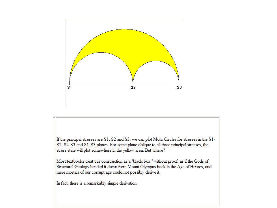
Mohr’s Circle? There is no Mohr’s circle solution for problems of triaxial stress state Solution for maximum principal stresses and maximum shear stress is analytical Either closed form solution or numerical solution (or computer program) are used to solve the eigenvalue problem.
 are used to solve the eigenvalue problem.")
95
Maximum Shear Stresses
Absolute max shear stress is the numerically larger of: ty’z’, tabs max tx’y’ ty’z’ s1 s2 s3 After finding the principal stresses, it is relatively easy to obtain the maximum shear stresses. Because no shear stresses act on the principal planes, it follows that an element oriented to the principal directions is in a state of triaxial stress. Therefore the three maximum shear stresses are: Normal Stress, s

96
3D Mohr’s Circle – Plane Stress
A Case Study – The two principal stresses are of the same sign s1 s2 s3 -s t

97
3D Mohr’s Circle – Plane Stress
A Case Study – The two principal stresses are of opposite sign s1 s2 s3 s t

98
y 80 MPa 50 MPa 120 MPa Tensor shows that: sz = 0 and t xz = t yz = 0
Example: For the following state of stress, find the principal and critical values. y 80 MPa 120 MPa 50 MPa Tensor shows that: sz = 0 and t xz = t yz = 0 x

99
The other 2 faces: y 80 MPa 0 MPa x 120 MPa 0 MPa z z

100
3-D Mohr’s Circles t max = 77 MPa Shear Stress, MPa

101
Example: triaxial stress state, not plane stress
Determine the maximum principal stresses and the maximum shear stress for the following triaxial stress state. (+ve values as defined in slide 1) s= MPa
 s= MPa.")
102
Solution s= = MPa = –10 = 40 MPa = MPa = MPa Solve

103
Results

104
Mohr’s circles Shear (MPa) ty’z’, tabs max=58.5 s2=26.5 s3=63.5
Normal Stress, s (MPa)
")
105
2. Max Principal Stress Criterion: smax= 63.5 MPa
Safety Factor? Not Required If the stress state was determined on a steel crankshaft, made of forged SAE1045 steel with a yield strength of 300 MPa, what is the factor of safety against yield? Tresca Criterion: tmax= 58.5 MPa 2. Max Principal Stress Criterion: smax= 63.5 MPa

106
NOT REQUIRED 3. Von Mises Criterion: = MPa

107
Yield criterion

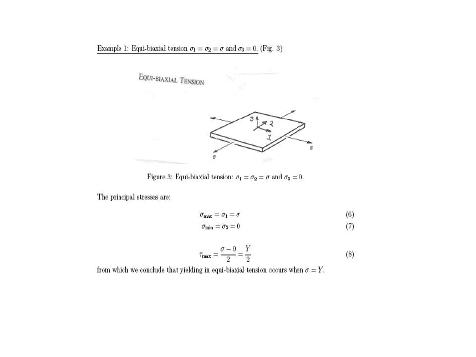
108
For simple tension

109
Tresca yield locus

127
Flow rules

131
Prove it Ignoring the Shear strains

134
Efficiency = ideal work / (total work)
")
136
Next lecture problems and solutions for two lectures
And tutorials

137
Using abacus, the program is a finite element software for
Modelling and analysis of Manufacturing processes We will use it to understand the operations and its analysis

Similar presentations


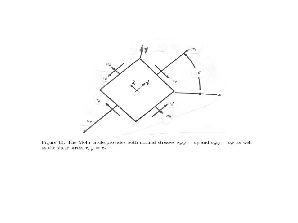


, the normal stress (sn) and the shear stress (ss), could be given by equations.>")
 Spring 2008>")


 Spring 2008 Dr. Konstantinos A. Sierros.>")


>")
