Download presentation
Presentation is loading. Please wait.

1
Fault Locating Overview
965AMS Fault Locating Overview Presented by Gary Morris

2
Outline Fault Locating RFL TDR

3
Fault Locating When to Use TDR and RFL
Opens and TDR for Capacitive Faults RFL and TDR for Resistive Faults

4
When to Use TDR or RFL You should know what fault or condition you have before trying to isolate with the RFL or TDR. TDR RFL Load Coil Yes No Tip/Ring Open Water Bridge Tap High Res Opens Short = or < 500 Ohms Tip Ground Ring Ground Battery Crosses

5
TDR Press the TDR key Choose Setup to enter cable information.
When finished choose a test and press OK

6
TDR Trace Examples - Open
Here is a pair the is open at 1780 feet.

7
TDR Tip Open Here is a pair the has an open tip open at 780 feet.

8
TDR Series Resistance Here is a pair the has a high resistance open at 950 feet.

9
TDR Short Here is a pair the has an short at 1000 feet.

10
TDR Water Approximately 100 Feet of water.

11
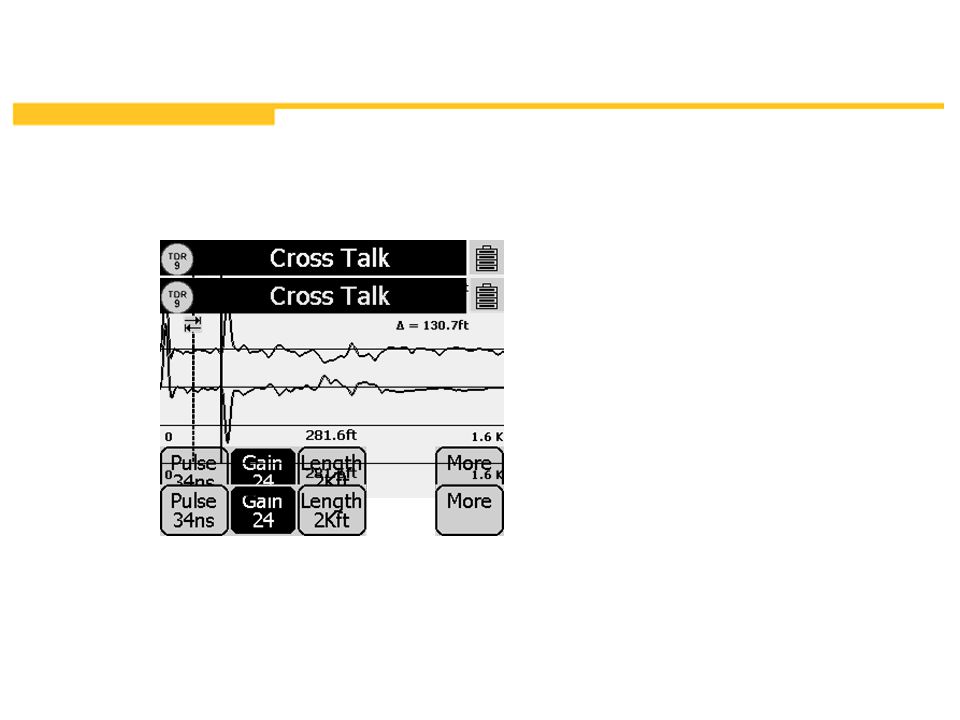
Expert Pair Test

12
RFL Fault Locating Tips
RFL test is used for faults under 20 mΩ. Always draw a diagram of the fault for better analysis. There three factors that is always involved in RFL (Resistance Fault Locating) - Gauge, Length and Temperature of the cable. Any two of the three must be known for RFL to work. The best option is to know the Gauge and Length of the section under test and the test set will compute the cable temperature. This is done during RFL Setup. A pair may have some light faults in it but it can be used as a ‘Good Pair’ as long as the light fault is at least 200 times better than the magnitude of the fault in the faulted pair. Ex: If the fault on a pair is 1 kilo-ohms, a pair with a 200 kilo-ohm fault can be used as a good pair. Of course, the higher the magnitude, the better. For best RFL accuracy , make a long cable section shorter by going to the middle of the section and open the pair to cut it in half. Check for the fault in one direction and then the other and then isolate the clean side. Repeat the process until the cable section becomes short enough where the following becomes practical: the length of a short section can easily be measured physically with a roller tape. If gauge and section length are known, the test set will compute cable temperature. With a short cable section, the use of a reel of jumper wire as a “Good Pair” placed above ground is now possible, instead of digging into the cable for a good one. Saves time. With a separate good pair and knowing the gauge and length of the section is the best and most accurate RFL option. In a ‘Single Pair Hookup’, the best good conductor to use is the mate of the faulted one and the next best is any good conductor from any of the adjacent pairs in the same group. Ex: If a pair has TIP(A) is faulted and RING(B) is good, RING(B) is then the best good conductor to use to shoot the fault on TIP(A). If DTF (Distance-To-Fault) and DTS (Distance-To-Strap) are equal, the fault is either at the strap or beyond.
 - Gauge, Length and Temperature of the cable. Any two of the three must be known for RFL to work. The best option is to know the Gauge and Length of the section under test and the test set will compute the cable temperature. This is done during RFL Setup. A pair may have some light faults in it but it can be used as a ‘Good Pair’ as long as the light fault is at least 200 times better than the magnitude of the fault in the faulted pair. Ex: If the fault on a pair is 1 kilo-ohms, a pair with a 200 kilo-ohm fault can be used as a good pair. Of course, the higher the magnitude, the better. For best RFL accuracy , make a long cable section shorter by going to the middle of the section and open the pair to cut it in half. Check for the fault in one direction and then the other and then isolate the clean side. Repeat the process until the cable section becomes short enough where the following becomes practical: the length of a short section can easily be measured physically with a roller tape. If gauge and section length are known, the test set will compute cable temperature. With a short cable section, the use of a reel of jumper wire as a Good Pair placed above ground is now possible, instead of digging into the cable for a good one. Saves time. With a separate good pair and knowing the gauge and length of the section is the best and most accurate RFL option. In a ‘Single Pair Hookup’, the best good conductor to use is the mate of the faulted one and the next best is any good conductor from any of the adjacent pairs in the same group. Ex: If a pair has TIP(A) is faulted and RING(B) is good, RING(B) is then the best good conductor to use to shoot the fault on TIP(A). If DTF (Distance-To-Fault) and DTS (Distance-To-Strap) are equal, the fault is either at the strap or beyond.")
13
RFL TIPS The use of a “Separate Good Pair”
is always the most accurate way to locate any type of a resistance fault.

14
Resistance Faults GROUND : A fault between ‘Tip [A]’ and ‘Ground’, ‘Ring [B]’ and ‘Ground’ or both conductors and ‘Ground’.
![Resistance Faults GROUND : A fault between ‘Tip [A]’ and ‘Ground’, ‘Ring [B]’ and ‘Ground’ or both conductors and ‘Ground’.](http://slideplayer.com/slide/3538748/12/images/14/Resistance+Faults+GROUND+%3A+A+fault+between+%E2%80%98Tip+%5BA%5D%E2%80%99+and+%E2%80%98Ground%E2%80%99%2C+%E2%80%98Ring+%5BB%5D%E2%80%99+and+%E2%80%98Ground%E2%80%99+or+both+conductors+and+%E2%80%98Ground%E2%80%99..jpg "Resistance Faults GROUND : A fault between ‘Tip [A]’ and ‘Ground’, ‘Ring [B]’ and ‘Ground’ or both conductors and ‘Ground’.")
15
Resistance Faults Cont..
SHORT : A fault between ‘Tip [A]’ and ‘Ring [B]’ conductors.

16
Resistance Faults Cont..
Battery CROSS : A fault between a working pair and a non-working pair (pair under test). Water -48 VDC -7 VDC Resistive Cross fault Pair # 1 - Working pair Pair # 1 - Working pair Pair # 2 - Non-working (Pair under test) -48 VDC -46 VDC Solid Cross Fault
. Water. -48 VDC. -7 VDC. Resistive Cross fault. Pair # 1 - Working pair. Pair # 1 - Working pair. Pair # 2 - Non-working. (Pair under test) -48 VDC. -46 VDC. Solid Cross Fault.")
17
RFL Hookup Examples Resistance Fault Locate 4-10
Press: to choose the type of hookup (single pair) or (separate good pair). Note: Defaults to the last setup. Explain: The clip and strap hookups. The user now hooks up the test set at the near end, and the strap at the far end. Press: to setup for Single Pair Hookup. 1015 Simulator: Turn Switch #3 ON; Hookup test set clips to terminal #1; Hookup Strap at terminal #5. Tip of pair 2 is Good Ring of pair 2 is faulted 10K Ohms Ground. Press: to use the setup and measure. Go to the next slide.
 or (separate good pair). Note: Defaults to the last setup. Explain: The clip and strap hookups. The user now hooks up the test set. at the near end, and the strap at the far end. Press: to setup for Single Pair Hookup Simulator: Turn Switch #3 ON; Hookup test set clips to terminal. #1; Hookup Strap at terminal #5. Tip of pair 2 is Good. Ring of pair 2 is faulted 10K Ohms Ground. Press: to use the setup and measure. Go to the next slide.")
18
telephone jacketed wire
“Separate Good Pair” It can be any pair of any gauge, longer or shorter than the faulted one, it doesn’t matter. For short cable section lengths (1000 feet or less), the good pair can be a reel of a CO jumper wire or a telephone jacketed wire placed above ground. Reel of CO jumper wire or telephone jacketed wire End-2 Good Pair Good Pair End-1 Faulted Pair Strap Ground Fault Near-End Shield/Ground Far-End
, the good pair can be a. reel of a CO jumper wire or a telephone jacketed wire placed above ground. Reel of CO jumper wire. or. telephone jacketed wire. End-2. Good Pair. Good Pair. End-1. Faulted Pair. Strap. Ground Fault. Near-End. Shield/Ground. Far-End.")
19
from another cable adjacent to the cable with the faulted pair.
“Separate Good Pair” It can be any pair of any gauge, longer or shorter than the faulted one, it doesn’t matter. For long cable section lengths (several thousand feet), the good pair can come from another cable adjacent to the cable with the faulted pair. End-2 Good Pair Good Pair End-1 Strap Fault Common Faulted Pair Faulted Pair Short Near-End Far-End
, the good pair can come. from another cable adjacent to the cable with the faulted pair. End-2. Good Pair. Good Pair. End-1. Strap. Fault. Common. Faulted Pair. Faulted Pair. Short. Near-End. Far-End.")
20
How To Extend The “Far-End Strap” If Necessary
Reel of CO jumper wire or telephone jacketed wire or any two wires, same length (any gauge) Good Pair [ from a distant cable ] Strap extension End-1 End-2 Far-End Strap Common Faulted Pair Short Near-End Far-End
 Good Pair [ from a distant cable ] Strap extension. End-1. End-2. Far-End Strap. Common. Faulted Pair. Short. Near-End. Far-End.")
21
RFL Single Section Setup
Choose fault type. Choose single pair or separate pair. Select single or multiple section. Choose the gauge. Length or temperature must be “unknown.” T-G R-G Short Tip Cross Ring Cross Wet Pulp

22
RFL Multiple Section Setup
Choose fault type. Choose single pair or separate pair. Select single or multiple section. Choose the gauge. Length or temperature must be “unknown” on last section. T-G R-G Short Tip Cross Ring Cross Wet Pulp

23
Estimating Cable Temperature
Aerial Cable: 1. If cable is not in direct sunlight. Add 20oF to the air temperature. 2. If cable is in direct sunlight. Add 40oF to the air temperature. Buried Cable: 1. Use temperature of tap water (city water). Let water flow out of a water faucet for several minutes and then measure the temperature. 2. In cold climates, use soil temperature at cable depth.
. Let water flow out of a water faucet for several minutes and then measure the temperature. 2. In cold climates, use soil temperature at cable depth.")
24
RFL Cont.. Press setup to change section 1 from 24 awg to 26 awg. ft 234.8 ft 3406 ft

25
Distance To Strap (DTS) = 4000 feet
Distance To Fault (DTF) = 2500 feet Strap To Fault (STF) = 1500 feet The bridge tap does not affect this reading. 1000 ft 3000 ft 500 ft 400 ft
 = 2500 feet. Strap To Fault (STF) = 1500 feet. The bridge tap does not affect this reading ft ft. 500 ft. 400 ft.")
26
Distance To Strap (DTS) = 4000 feet
Distance To Fault (DTF) = 1000 feet Strap To Fault (STF) = 3000 feet Fault measures here! 1000 ft 3000 ft 500 ft 400 ft
 = 1000 feet. Strap To Fault (STF) = 3000 feet. Fault measures here! 1000 ft ft. 500 ft. 400 ft.")
27
Distance To Strap (DTS) = 3900 feet Distance To Fault (DTF) = 400 feet
Strap To Fault (STF) = 3500 feet Fault measures here! 1000 ft 3000 ft 500 ft 400 ft
 = 3500 feet. Fault measures here! 1000 ft ft. 500 ft. 400 ft.")
28
Questions ? Live Demo

29
Option 3

Similar presentations


![L 25 Electricity and Magnetism [3] Electric circuits what conducts electricity what doesn’t conduct electricity Current, voltage and resistance –Ohm’s.](/14/4347799/big_thumb.jpg "L 25 Electricity and Magnetism [3] Electric circuits what conducts electricity what doesn’t conduct electricity Current, voltage and resistance –Ohm’s.>")


![L 26 Electricity and Magnetism [3] Electric circuits Electric circuits what conducts electricity what conducts electricity what doesn’t conduct electricity.](/20/6043487/big_thumb.jpg "L 26 Electricity and Magnetism [3] Electric circuits Electric circuits what conducts electricity what conducts electricity what doesn’t conduct electricity.>")


