Download presentation
Presentation is loading. Please wait.

1
Introduction to Robot Subsystems
Presented By: Funky Monkeys, Team 846 Available online at lynbrookrobotics.com Resources > WRRF Presentations

2
Choosing the Right DriveTrain
Presented by: Miles Chan I am Miles Chan, and I would like to talk to you about choosing the right drivetrain for your FRC robot. A drivetrain is the system responsible for moving your robot.

3
Drivetrain Requirements
Common Features: Fast Easy to turn High acceleration FIRST Competition Demands: Point-to-point movement Turn in place Push hard

4
Ackerman Steering Team 34’s Design on Chief Delphi
Distinction between common for frc and everyday Team 34’s Design on Chief Delphi

5
Differential/Tank Steering
Power left and right sides independently Features Simple Easy to drive Pushes hard Swap picture… comment that not only treads we have wheels same concept

6
4 Wheels Differential Steering
Wheels slide to turn Bt how well does this work???? Lets look at some math.

7
Ability to Turn Turning Torque – Resisting Torque
Wheels generate force while friction resists Turning Torque – Resisting Torque

8
Terminology: µ = Coefficient of Friction Weight = Weight of the robot
Track (W ) µ = Coefficient of Friction Weight = Weight of the robot F = Force T = Torque Wheelbase (L)
 µ = Coefficient of Friction. Weight = Weight of the robot. F = Force. T = Torque. Wheelbase. (L)")
9
Maximum Tractive Force Per Wheel (FTMax)
Track (W ) Wheelbase (L) Let’s say that the maximum tractive force that your robot exerts on the ground is 80 pounds. If your gearmotors can apply 150 pounds of force, what’s going to happen?
 Wheelbase. (L) Let’s say that the maximum tractive force that your robot exerts on the ground is 80 pounds. If your gearmotors can apply 150 pounds of force, what’s going to happen")
10
Maximum Turning Torque (TTMax)
Track (W ) W/2 Wheelbase (L) Loosely speaking, torque is a measure of the turning force on an object such as a bolt or a flywheel. For example, pushing or pulling the handle of a wrench connected to a nut or bolt produces a torque (turning force) that loosens or tightens the nut or bolt.
 W/2. Wheelbase. (L) Loosely speaking, torque is a measure of the turning force on an object such as a bolt or a flywheel. For example, pushing or pulling the handle of a wrench connected to a nut or bolt produces a torque (turning force) that loosens or tightens the nut or bolt.")
11
Maximum Resisting Torque (TResisting)
Track (W ) L/2 Wheelbase (L)
 L/2. Wheelbase. (L)")
12
Turning Torque v. Resisting Torque

13
4 Wheel Layout Remember: Turning Force – Resisting Force
Only wide robots can turn What are the disadvantages of having a short wheelbase? How can you have the stability of a long wheelbase with the ability to turn of a short wheelbase?

14
6 Wheel Layout Weight spread over 6 wheels
Only 4 wheels resist turning View the slide with the animations.

15
Turning Torque v. Resisting Torque

16
6 Wheels Dropped Center Center wheels dropped about 1/8 inch
Improvement of 33% - 100% Rocks on center when turning 10% But now lets look at some other ways to make robots turn more easily 30% 10%

17
2 Wheels, 2 Omniwheels Omniwheels
c 2 Wheels, 2 Omniwheels Omniwheels 90° rollers allow sideways motion Center of rotation between non-omni wheels 4 wheels provide tractive force No Wheels Resist Please view this slide as it will be animated during the presentation or slide the omniwheel over to see the text.

18
Swerve Drive Wheel modules rotate Advantages Disadvantages
Translational movement Pushes hard Disadvantages Complicated design Increased need for driver training Requires additional steering motor Craig Hickman’s Design on Chief Delphi

19
Mecanum Wheels 45° Rollers allow lateral movement

20
Mecanum Drive Advantage Disadvantage
Demo: eature=related Advantage Translational movement Disadvantage More gearboxes Expensive wheels Low pushing force

21
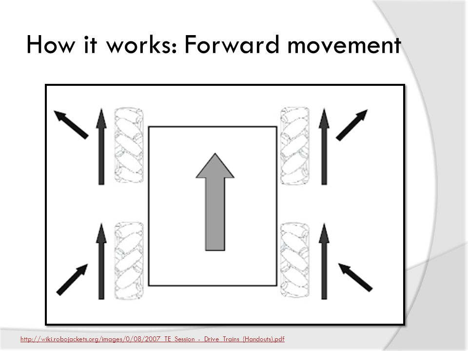
How it works: Forward movement
22
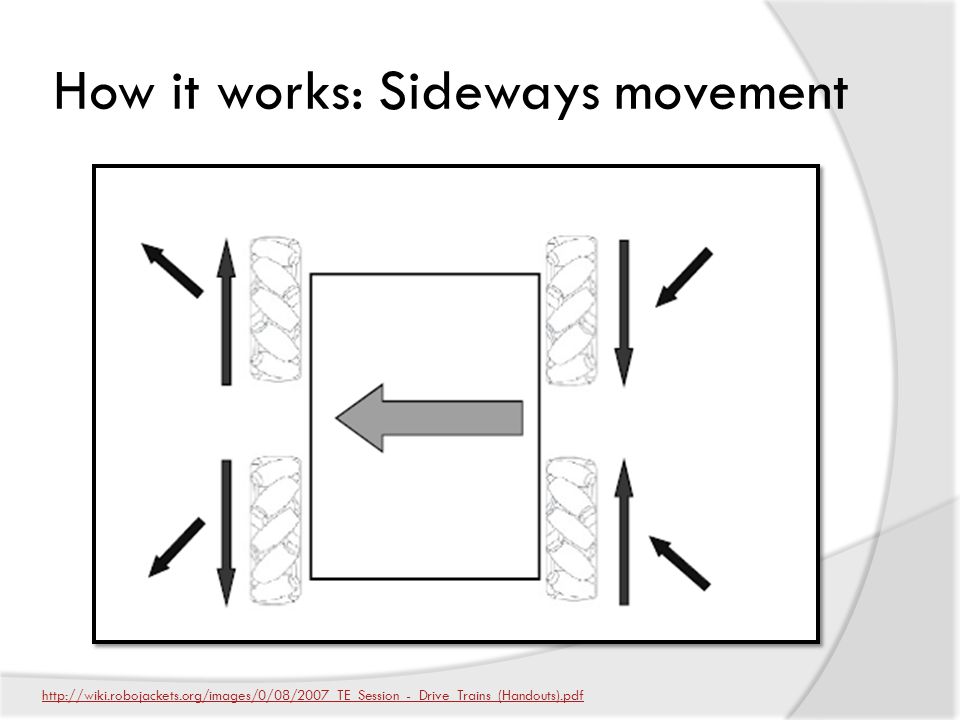
How it works: Sideways movement
23
Videos Omni, Mecanum, Swerve drive examples
Nona-drive (variant of Slide Drive) feature=related
 v=_hTyXQUgYLE& feature=related.")
24
Conclusion Exotic Drives Tank Drivetrain Cool factor
May give key advantage in a particular game. Tank Drivetrain Simple solution - rugged & reliable Irfanview

25
Electrical Subsystem Presented by: The Funky Monkeys Team 846
Akshat Agrawal, Anurag Makineni, and Jackie Zhang Electrical = power distribution + power control Electronics = low power sensors and circuits BDCComm

26
Power Distribution Diagram
Robot Controller Make motor in the corner smaller to resemble scaling Make CPU darker Put red/black lines closer together Put currents for the branches – CPU = 20 A, Spike = 20 A, Speed Controller = 40 A,

27
Battery 12V Lead Acid Battery (18Ah) 13 Pounds
Provides over 100 amperes of current. Total output of over watts of power. Can supply over 700 amperes of current when terminals are shorted. Explain battery safety Two hands because it is heavy Nylon stop nut is a tip Remove #10 screw - done Smaller than a car battery Fix spacing Remove bullet point for take precautions Change text NEED TO SAY Terminals are separate Wrench Welded together

28
Robot Power Switch Used to turn robot on and off, including emergency shut off Also a 120 amp circuit breaker Must be placed in an accessible location Not located accessibly Should be in an easy-to-access area On/Off switch Fire hazard Retitle to robot power switch 120 amp circuit breaker Control should be changed to limit Exceed 120 amps and it will break Remove bullet points when not necessary High current switch Handles high enough current Primary importance Doubles as a circuit breaker

29
Power Distribution Board
Main Power Circuit connection 20-40 Ampere Fuse Location Branch circuit power connection

30
DC To DC Converters Used to change voltage coming from battery to specific voltage required in branch circuit 12V-5V 12V-24V (for robot controller)
")
31
Power Distribution Diagram
18AWG Robot Controller 100A 6AWG 40A 20A 12AWG 18AWG Make motor in the corner smaller to resemble scaling Make CPU darker Put red/black lines closer together Put currents for the branches – CPU = 20 A, Spike = 20 A, Speed Controller = 40 A,

32
American Wire Gauge Sizes are based on the AWG (American Wire Gauge) System AWG sizes are based on number of wire draws – Higher gauge = thinner wire Explain safety concerns when using smaller diameter wires

33
CCL Industrial Motors Limited (CIM)
Motors (FRC 2011) Name # in KOP Additional Allowed Total CIM 2 4 BaneBots Fisher Price 1 Window Motors Worm Gear Automotive Window Motor Replace with collection of motors Only allowed to use motors inside the kit Be aware that the rules may specify that you can buy extra motors (of the same type) Discuss major types of motors FIX: scaling of pictures Mabuchi is the motor on the left Caption Properly identify with companies CIM = CCL industrial motor Johnson electric motors for FP Mabuchi CCL Industrial Motors Limited (CIM) RS Series Motor
 Name. # in KOP. Additional Allowed. Total. CIM BaneBots. Fisher Price. 1. Window Motors. Worm Gear. Automotive Window Motor. Replace with collection of motors. Only allowed to use motors inside the kit. Be aware that the rules may specify that you can buy extra motors (of the same type) Discuss major types of motors. FIX: scaling of pictures. Mabuchi is the motor on the left. Caption. Properly identify with companies. CIM = CCL industrial motor. Johnson electric motors for FP. Mabuchi. CCL Industrial Motors Limited (CIM) RS Series Motor.")
34
Robot Controller CompactRio National Instruments Embedded Controller
The “Brain” of the robot Sends control signals to components In 2012, rookie teams will receive new smaller cRIO. Costs $525 for veteran teams Costs $285 without I/O modules Servo testers at hobby stores to generate control signal for ESCs Speaking Servo is closed loop motor control Expand ESC Fix CPU darkness

35
cRIO Specs 2012 cRIO-4 Slots Power Proccessor Memory Software
24V Power via PD Board Proccessor 400 MHz Freescale MPC5125 Memory 256MB System Memory 512MB Storage Memory Software VXWorks Operating System Lab View, C++, Java Has an Field Programmable Gate Array (FPGA) allows for real time access to the robot
 allows for real time access to the robot.")
36
PROBLEM! The cRIO cannot directly control the motors. Solution
Cannot provide enough power – will get fried if that much power runs through it. Solution Intermediary Motor Controllers Relays Electronic Speed Controllers

37
Spike Relays Relays close or open the circuit based on signals from the cRIO. Use an H-Bridge

38
How an H-Bridge Works S1+S4 FULL FORWARD S3+S2 FULL REVERSE S1+S3
BRAKE S1 S3 MOTOR S2 S4 Ground

39
Electronic Speed Controller (ESC)
Control the amount of power sent to the motors in addition to direction that motor turns. Two types of ESC’s: Victor 884 ESC Jaguar ESC 2004+ Victor 2009+ Jaguar

40
Speed Controller Comparison
Victor ESC Smaller Communication via: Servo Wire Jaguar ESC Larger Communication via: Servo Wire CAN-bus 2004+ Victor 2009+ Jaguar

41
Pulse Width Modulation (PWM)
Pulse Width Modulation is used in two ways on our FIRST Robots: To provide a varying amount of power to the motors. To communicate with the Speed controller.

42
Variable Power Delivery
The Speed Controller varies the power delivered to the motors by changing the “Duty Cycle.” DUTY CYCLE (%) = TIME ON PERIOD 12V 0V DUTY CYCLE PERIOD (ms) 12V 0V
 = TIME ON. PERIOD. 12V. 0V. DUTY CYCLE. PERIOD (ms) 12V. 0V.")
43
Speed Controller Communications
There are two ways to communicate with the ESC CAN-bus Uses “Message based protocol” (like Ethernet) Servo Cable Uses Pulse Width Modulation
 Servo Cable. Uses Pulse Width Modulation.")
44
Speed Controller Communications using PWM
RC Model Aircraft standard: The width of the pulse is measured as unit of time. Time which each pulse lasts is the pulse width. Signal: 2.0 ms = full forward 1.75 ms = 50% fwd 1.5 ms = off 1.0 ms = full reverse 1.5 ms 0.5 ms Voltage applied only 50% instead of power Variable resistor first On and off so no mechanical switch Transistor Introduce new slide for communication (see bottom of these notes) Remove odd picture Radio control signal for the Victor Describe frame from 20ms to 40ms PWM communication Immune to electronic noise Introduce slide for communication Spike with three wires - 3 wire servo cable Victor/Jag use PWM data signal + description Jaguar also has data communication port for the CAN-Bus 40 ms (20ms-50ms)
 Remove odd picture. Radio control signal for the Victor. Describe frame from 20ms to 40ms. PWM communication. Immune to electronic noise. Introduce slide for communication. Spike with three wires - 3 wire servo cable. Victor/Jag use PWM data signal + description. Jaguar also has data communication port for the CAN-Bus. 40 ms. (20ms-50ms)")
45
CAN-Bus “CAN” Stands for “Controller Area Network”
Is a single chain of point-to-point connections The “bus” goes around the chain delivering the signal to different addresses – each ESC has its own address cRIO 2 CAN ESC ESC ESC ESC ESC ESC ESC ESC

46
How does the CAN-bus simplify wiring?
ESC cRIO 2 CAN ESC cRIO (Daisy Chaining) Although the amount of wires is the same in each case, without the CAN-bus, the wires have to stretch all the way across the robot from the cRIO to each ESC, whereas with the CAN-bus, they are all linked together in a single chain.
 Although the amount of wires is the same in each case, without the CAN-bus, the wires have to stretch all the way across the robot from the cRIO to each ESC, whereas with the CAN-bus, they are all linked together in a single chain.")
47
CAN-Bus Wiring Telephone-style RJ11 instead of servo wire
Easy to make custom length with crimp tool Can’t be put in backwards Servo Wire Called servo wire because it is used to connect to the servos of remote-controlled vehicles NEED TO SAY Servo wire coming loose Crimper cheap at Radio Shack/Home Depot Telephone Wire

48
Power Distribution Diagram
Robot Controller Make motor in the corner smaller to resemble scaling Make CPU darker Put red/black lines closer together Put currents for the branches – CPU = 20 A, Spike = 20 A, Speed Controller = 40 A,

49
Sensors and Electronics
Presented by: Brian Axelrod Manual vs Automation

50
Sensors and Electronics
Presented by: Brian Axelrod Manual vs Automation

51
Why use sensors?

52
Why use sensors?

53
Why use sensors? Increased performance Safety Speed Preset Positions
Prevent robot from damaging itself

54
Limit switch A simple switch
Can be set up to be triggered near a physical limit $

55
Hall effect sensor Detects a magnetic field Longer range
Can switch much faster than a mechanical switch $

56
Potentiometers (Pots)
Sensor for measuring position: Rotation, distance, etc. $

57
Potentiometers (Pots)
Slider is connected to output. Simplest type: Slider +5V +5V +5V GND Output 5V 100% 2.5V 50% 10 KΩ 0V 0% Ground/0V Ground/0V

58
Types of Potentiometers (pots)
Slide Rotary

59
Pots: Uses Sense position: e.g. lift How to sense the lift position?
Travel length is 6 feet No linear pot long enough

60
Multi-turn Pots Multi-turn pot: Alignment is important!
Usually 3, 5, or 10 turns $$ Alignment is important! Continuous rotation: use encoder Move pot picture

61
Reading the Value Analog voltage level
Analog-to-Digital Converter (ADC) Converts to number for 10-bit ADC Comes in kop with cRio as analog module 8 ports Easy to implement in code m_liftPot.GetAverageValue()
 Converts to number for 10-bit ADC. Comes in kop with cRio as analog module 8 ports. Easy to implement in code. m_liftPot.GetAverageValue()")
62
Optical Encoders to controller Optical Sensor (A) to controller
Optical Sensor (B) to controller Improve animation and show waveform Angles? More than one tick Directions Spin animation A Channel B Channel
 to controller. Improve animation and show waveform. Angles More than one tick. Directions. Spin animation. A Channel. B Channel.")
63
Optical Encoders to controller Optical Sensor Optical Sensor
Brush over Just more ticks Remove optical sensor Optical Sensor to controller

64
Optical Encoders Determining Distance Travelled Determining Speed
Count pulses Determining Speed Distance over time Time over distance Do in one slide just say two different ways

65
Other Encoders Our 2006 robot’s ball launcher
Hall Effect Sensor, and embedded magnet in wheel Our 2006 robot’s ball launcher Make your own encoders Don’t need quadrature using encoder as a speed sensor

66
Yaw Rate Sensor/Gyro Also commonly known as a gyro
Indicates rotational velocity

67
Accelerometer Measures acceleration Detects gravity
Going above max acceleration will give you wrong readings Detect if going up a bump straight

68
Sensing Distance: Ultrasonic Sensors
Determine distance Send pulse of sound Measure time until echo CONS such as sensitivity to soft and irregular surfaces Noisy environment may cause problems

69
Infrared Proximity Sensors
Determines distance to object in front of it Analog voltage reading vs. ultrasound: Shorter range More accurate Sensing game pieces inside your robot Short range non contact sensing

70
Camera Not a magic bullet Can choke your machine Image processing
Can sense enviroment CAUTION

71
Kinect Still not a magic bullet RGB-D
With proper processing easier to make reliable Depth image not dependant on lighting CAUTION

72
Conclusion Never rely on the operator to do the right thing
Useful for adding functionality and as safety features Large variety of sensors that can detect a variety of parameters Can buy sensors at Trossen robotics Digi-key Mouser Acroname

73
Pneumatics Michael Lin and Eric Yeh presents…
Presenter: Michael Lin + Eric EY: Hello My name is Eric ML: Hello My name is Michael, and we are here today to talk about the pneumatics subsystem.

74
Pneumatics - Definition
Pneumatics is the use of pressurized air to achieve mechanical movement Presenter: Michael Lin Pneumatics is commonly confused with hydraulics. - Difference = pneumatics uses are and Hydraulics uses oil. Key difference FIRST does not allow use of hydraulics. But they do allow use of pneumatics Drill Nail gun Jack Hammer Pneumatics?

75
Overview of Pneumatics
Presenter: Michael Lin -compressor generate pressure -actuator transform pressure to motion -solenoid controls the motion -tubings and fittings to let the air flow -above is everything we need, to generate motion, but it is not safe and reliable -regulators are used to transform stored air pressure to working pressure -value for safety, is the pressure’s sensor which if sense too much pressure it will release the air, so the system won’t explode

76
From FIRST pneumatics manual
Presenter: Michael Lin Lets start with what powers the entire system; the compressor. From FIRST pneumatics manual

77
Compressor Source of energy in pneumatic system Compacts air
Can Generate up to 120 PSI Compacts air Presenter: Michael Lin This is the Compressor (Denver Gardner Thomas pump) that FIRST provides to rookie teams. This is what gives the pneumatic system its energy by compacting air. Diaphragm compressor, axial compressor (turbine), piston compressor
 that FIRST provides to rookie teams. This is what gives the pneumatic system its energy by compacting air. Diaphragm compressor, axial compressor (turbine), piston compressor.")
78
Diaphragm pump Presenter: Michael Lin
DEMO notes: Lets see the pump in action. What we have here is your typical compressor that’s powered by a battery. This is the output of the compressor, and when I turn this plug valve to seal this port, we have an enclosed space that the compressor pumps air into. *hits the switch* This pressure gauge here indicates the pressure at the output of the compressor. When the pressure of the output has reached a certain limit, typically 120 psi, this electrical pressure switch here would open, and that would turn off the compressor. You can hear the compressor pulsing every now and then. We unfortunately have small leaks in the system that vents pressurized air. When this pressure switch detects that the pressure has dropped below a certain value, typically 115 psi, it would close and turn the compressor back on.

79
From FIRST pneumatics manual
Presenter: Michael Lin Lets start with what powers the entire system; the compressor. From FIRST pneumatics manual

80
Common Valves and Fittings
Pressure switch, Release valve, Plug valve, Presenter: Michael Lin Notice this cylinder. On this end it has a common L join, but the one on this side has a screw on top. This is a flow-rate valve. <explanation> Because of this, you can fit two of these valves on the cylinder and that allows you to independently control the extending and retracting speeds. *Make sure to make it a point that a team will only need to use on type of valve. All valves here are just types of valves that can be used.

81
From FIRST pneumatics manual
Presenter: Michael Lin Now lets say we want 60 psi but from before we know that if we feed the pressurized air directly to the system we would be outputting more than that. How would we achieve this daunting task? By adding a regulator! Now that we see the basics behind pneumatics, we want to know how to usefully incorporate it into our robot when we’re designing it. To do this, we need to control several factors that affect the mechanics of actuators. The first factor is output pressure. From FIRST pneumatics manual

82
Regulator Maintains a constant level of pressure.
Working air pressure Maximum of 60 psi for FIRST competitions Presenter: Michael Lin You can see here that the pressure at the output of the compressor is at 120 psi, but FIRST only allows us to operate our actuators at a maximum of 60 psi. We achieve this pressure drop by using a regulator. It drops the input pressure to an output pressure that you can set by turning this knob. This gauge above the regulator shows pressure that being outputted.

83
From FIRST pneumatics manual
Presenter: Eric Yeh Now lets see where the energy of the compressed air is used to get mechanical motion. It’s achieved through these objects, called actuators. From FIRST pneumatics manual

84
Actuators Actuators convert the difference in air pressure to mechanical motion Takes the working air and makes it into mechanical motion Linear actuators (also known as cylinders) Narrower actuators move more quickly Presenter: Eric Yeh An important note to remember is that the actuator applies full force when the piston isn’t moving.
 Narrower actuators move more quickly. Presenter: Eric Yeh. An important note to remember is that the actuator applies full force when the piston isn’t moving.")
85
From FIRST pneumatics manual
Presenter: Eric Yeh Now that we see the basics behind pneumatics, we want to know how to usefully incorporate it into our robot when we’re designing it. To do this, we need to control several factors that affect the mechanics of actuators. The first factor is output pressure. From FIRST pneumatics manual

86
Solenoid Valves Controlled by the robot’s CPU
Solenoids opens a port to pressure when a voltage is applied Double solenoids controls two ports When one port is open, the other is closed Presenter: Eric Yeh You see how we controlled which way the cylinder moves with a click of a button. Often times we also want to control when we send compressed air to the cylinders or through which ports. For example, suppose you have a pneumatic pistons that you want to use a cylinder to lift something at the finale. We do this with electric solenoid valves. Although these valves are controlled electrically by the robot’s CPU, they can also be mechanically operated by pressing these buttons. A single solenoid valve allows you to open one port of a cylinder to pressure when voltage is applied, or when I press this button, causing the cylinder to either extend or retract. When voltage is no longer applied, the valve releases the pressure to atmosphere, and whatever load is on the piston will cause it to return to its original position. A double solenoid valve allows you to use the cylinder in both directions. When I press this button or when voltage is applied to this solenoid, the valve would open the blue side to atmosphere and the white side to pressurized air, causing the cylinder have an extending force. When the other solenoid is activated, the white side is open to atmosphere and the blue side to pressurized air, causing the cylinder to have a retracting force. Festo single solenoid valve Festo double solenoid valve

87
From FIRST pneumatics manual
Presenter: Michael Lin When we try and apply pneumatics to our FIRST Robots we can not have a compressor on the robot compressing air constantly to meet our demands. So how can we get compressed air on our robots? We use tanks to store the air we need! we want to know how to usefully incorporate it into our robot when we’re designing it. To do this, we need to control several factors that affect the mechanics of actuators. The first factor is output pressure. From FIRST pneumatics manual

88
Tank Tanks are a reserve of compressed air
Maximum of 120 psi for First competitions Presenter: Michael Lin Plastic vs. Metal = weight concern How many movements can we do with one tank?

89
Finding Linear Force 𝐷 Presenter: Eric Yeh
What is area – pi x radius squared What is pressure – force divided by area What is force – pressure times area Lets calculate the amount of force which will be needed… 89

90
Finding Linear Force 𝐷 𝑑 Presenter: Eric Yeh
What is area – pi x radius squared What is pressure – force divided by area What is force – pressure times area Lets calculate the amount of force which will be needed… 𝑑 90

91
Finding Linear Force 𝐷 𝑑 Presenter: Eric Yeh
What is area – pi x radius squared What is pressure – force divided by area What is force – pressure times area Lets calculate the amount of force which will be needed… 𝑑 91

92
Forces of Different Bore Cylinders at 40 psi and 60 psi
Bore (inches) 0.75 1.50 2.00 Extending (40 psi) 18 lbf 71 lbf 126 lbf Retracting (40 psi) 16 lbf 65 lbf 113 lbf Extending (60 psi) 26 lbf 106 lbf 188 lbf Retracting (60 psi) 24 lbf 97 lbf 170 lbf Presenter: Eric Yeh Wasn’t doing all that math fun!? Well here is a table with basic numbers so you don’t need to do all that math again. From FIRST pneumatics manual
 Extending (40 psi) 18 lbf. 71 lbf. 126 lbf. Retracting (40 psi) 16 lbf. 65 lbf. 113 lbf. Extending (60 psi) 26 lbf. 106 lbf. 188 lbf. Retracting (60 psi) 24 lbf. 97 lbf. 170 lbf. Presenter: Eric Yeh. Wasn’t doing all that math fun! Well here is a table with basic numbers so you don’t need to do all that math again. From FIRST pneumatics manual.")
93
From FIRST pneumatics manual
Presenter: Michael Lin When we try and apply pneumatics to our FIRST Robots we can not have a compressor on the robot compressing air constantly to meet our demands. So how can we get compressed air on our robots? We use tanks to store the air we need! we want to know how to usefully incorporate it into our robot when we’re designing it. To do this, we need to control several factors that affect the mechanics of actuators. The first factor is output pressure. From FIRST pneumatics manual

94
Finding Linear Force 𝐴𝑟𝑒𝑎=𝜋 ∗𝑟 2 𝐷 𝑃𝑟𝑒𝑠𝑠𝑢𝑟𝑒= 𝐹𝑜𝑟𝑐𝑒 𝐴𝑟𝑒𝑎 𝐴𝑟𝑒𝑎=𝜋 ∗ 𝑑 2 2
𝐴𝑟𝑒𝑎=𝜋 ∗ 𝑑 2 2 𝐹𝑜𝑟𝑐𝑒=𝑃𝑟𝑒𝑠𝑠𝑢𝑟𝑒∗𝐴𝑟𝑒𝑎 𝐴𝑟𝑒𝑎= 𝜋 4 ∗ 𝐷 2 𝐹= 𝜋 4 ∗𝑃 𝐷 2 Presenter: Eric Yeh What is area – pi x radius squared What is pressure – force divided by area What is force – pressure times area Lets calculate the amount of force which will be needed… 𝐹= 𝜋 4 ∗𝑃 (𝐷 2 − 𝑑 2 ) 𝐴𝑟𝑒𝑎= 𝜋 4 ∗ (𝐷 2 − 𝑑 2 ) 𝑑 94
 𝐴𝑟𝑒𝑎= 𝜋 4 ∗ (𝐷 2 − 𝑑 2 ) 𝑑. 94.")
95
Conclusion Covered major components of FIRST robots
Slides available at lynbrookrobotics.com Resources > “WRRF Presentations”

Similar presentations


. Students should lead their teams in the building, design, and all other aspects of the robot. Knowledge of the Kit.>")


