Download presentation
Presentation is loading. Please wait.

1
Discover the Magic Of HF Radio

2
Welcome to Worldwide Communications
This presentation is designed to introduce the new or recently upgraded ham to HF radio.

3
Welcome to Worldwide Communications
The information presented here is very general.

4
Welcome to Worldwide Communications
More information can be found in the ARRL publications listed at the end of this program.

5
HF stands for HIGH FREQUENCY HF is also known as shortwave.
What Does HF Mean? HF stands for HIGH FREQUENCY These are the frequencies from 1.8* to 30 MHz or the 160 meter to 10 meter bands. HF is also known as shortwave. *160m is actually a Mid Frequency (MF) band but it is included in the Amateur HF bands for ease of discussion.
 band but it is included in the Amateur HF bands for ease of discussion.")
6
How is HF different than FM repeaters?
No “machine” or infrastructure is used.

7
How is HF different than FM repeaters?
Allows communication beyond line of sight. Contacts are generally a couple of hundred miles to over several thousand miles.

8
How is HF different than FM repeaters?
Propagation is strongly effected by solar activity.

9
How is HF different than FM repeaters?
Several communication modes are available to use. SSB, CW, RTTY, SSTV, Digital, AM

10
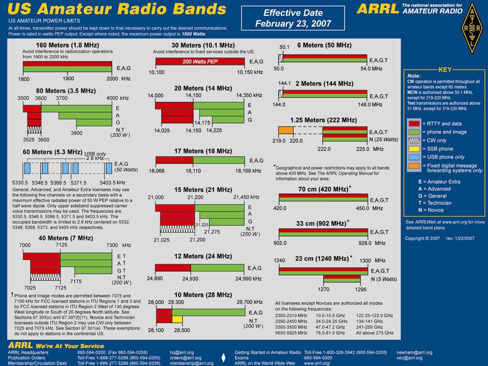
HF Band Allocation Meter Band Frequency (MHz) CW, RTTY, Data Voice 160
80 40 7.000 – 7.125 30 20 17 15 12 10

12
Who Uses HF? Because of the ability to communicate over long distances, HF is used by many government, military, and commercial agencies worldwide.

13
Who Uses HF? Amateur Radio operators all over the world use HF for the same reasons of being able to communicate over long distances.

14
Amateur Radio & HF When most people hear the term ham radio they generally think of HF or shortwave and long distance communications.

15
Who Has HF Privileges? In the United States all licensed Amateur Radio operators have privileges on the HF bands.

16
Who Has HF Privileges? Technician and Novice class licensees are permitted to operate CW on portions of the 80, 40, 15 and 10 meter bands.

17
Who Has HF Privileges? Technicians also have SSB and Data privileges on portions of the 10 meter band.

18
Who Has HF Privileges? Technician and Novice class licensees have power limitations on the HF bands.

19
Who Has HF Privileges? General, Advanced and Extra class licensees are permitted to use all available modes on the HF amateur bands.

20
Who Has HF Privileges? General, Advanced and Extra class licensees are also permitted to use full legal power.

21
HF is FUN With a 100 watt transceiver and a simple wire antenna, you can start to communicate and make friends with other hams all over the country or the world.

22
What this program covers
HF is FUN What this program covers

23
HF is FUN We will talk about how and why radio waves can travel great distances around the world.

24
HF is FUN We will talk about HF radios and some of their features and controls.

25
HF is FUN We will explain to you what some of the controls are on the radio and what it is that they do.

26
HF is FUN We will talk about simple antennas that are: very effective,
Inexpensive and easy to construct and install.

27
HF is FUN We will also talk about some of the ways that amateurs configure their antennas to affect where their signals are going to go.

28
HF is FUN Let’s Get Started

29
Hearing Signals Out of Thin Air

30
How It Works (Propagation)
Just as sailors use the natural forces and currents of wind and water to guide their boats,

31
How It Works (Propagation)
radio operators use naturally occurring charges in a layer of the atmosphere called the ionosphere to bend and reflect their radio signals.

32
Why It Works (The Atmosphere)
The Earth’s atmosphere is made up of several layers or regions.

33
Why It Works (The Atmosphere)
We are most concerned with the uppermost region called the ionosphere. *The ionosphere is part of the thermosphere and not a separate layer or region. For our discussion we will only refer to the layers that make up the ionosphere.

34
The Role of Sol How the Sun Opens and Closes The Bands

35
The Sun’s energy causes atoms in the upper atmosphere to become charged. These charged particles are called ions.

36
This charged region of the upper atmosphere is called the ionosphere.

37
When a radio wave enters this region of charged particles, its direction of travel is altered.

38
Radio waves change direction when they enter the ionosphere

39
The Ionosphere The ionosphere is broken up into layers.
These layers are the D, E and F layers.* *There is no A, B, or C layer. These were reserved for possible future discoveries.

40
The Ionosphere The Sun’s UV radiation charges these layers and this affects radio waves and how they travel.

41
The Layers of the Ionosphere

42
The D Layer The D Layer is the lowest and densest region of the ionosphere. It extends 37 to 57 miles above the Earth’s surface.

43
The D Layer Because of its density, the D-layer tends to absorb radio signals.

44
The D Layer The absorption of RF varies by wavelength. Longer waves such as 160m and 80m are most effected.

45
The D Layer D-layer effect is less on 40m, slight on 20m and inconsequential on the higher frequencies.

46
The D Layer The ionization level of this lower part of the atmosphere is directly related to the sunlight.

47
The D Layer Therefore, The D-layer begins at sunrise, peaks at noon and disappears at sunset.

48
The D Layer The Sun’s ionization of the upper atmosphere and creation of the D layer is what “closes” the low bands during the day.

49
The D Layer The disappearance of the D layer at sunset “opens” the low bands and they will remain open throughout the night.

50
The E Layer At 62 to 71 miles above the Earth, the E layer is the lowest portion of the ionosphere useful for long distance communications.

51
The E Layer Ionization of the E layer occurs rapidly after sunrise and diminishes quickly after sunset. Minimum ionization of the E layer is after midnight, local time.

52
The E Layer Like the D-layer, the E-layer absorbs long wavelength signals during the day.

53
The E Layer Signal absorption is highest when the sun is at it’s highest angle. (local noon)
")
54
The E Layer The E layer effects other Amateur bands above 30 MHz but for now we will limit our discussion to the HF bands.

55
The F Layer The F layer is the uppermost region of the atmosphere. It begins at approximately 100 miles and can extend to over 310 miles above the Earth’s surface.

56
The F Layer The F layer is responsible for most of our long distance communications.

57
The F Layer Because this region is so far away from the Earth’s surface it is less dense than the other regions.

58
The F Layer It often takes a while for noticeable effects of the Sun’s radiation to develop but the charges can last long after sunset.

59
The F Layer During the day in summertime the Sun’s radiation can cause the F layer to become two separate layers called F-1 and F-2 layers. The lower F-1 layer doesn’t last long after sunset.

60
The F Layer The effects of the Sun on the ionosphere change as the seasons change because the angle between the Sun and the Earth changes throughout the yearly cycle.

61
The F Layer In the summer, during periods of high solar activity, it is not unusual to see bands like 10 and 15 meters stay open until midnight and 20 meters stay open all night.

62
Skipping Signals In order to travel distances greater than “line of sight”, radio signals skip off the ionosphere and return to Earth.

63
Radio waves encountering the ionosphere above the critical angle don’t get bent enough to return to Earth. Waves entering at angles below the “critical angle reach the Earth at increasingly greater distances as the launch angle approaches horizontal.

64
Skipping Signals Like skipping a stone on a pond, if we send our signals off at very low angles they will make more hops and travel farther.

65
Skipping Signals HF operators will configure their antennas so that they can direct their signals where they want them.

66
Skipping Signals HF operators also know what frequency to use at different times of the day or season for effective communications.

67
Propagation Sky-wave Ground wave High Angle Radiation (NVIS)
There are three basic types of propagation of HF radio signals: Sky-wave Ground wave High Angle Radiation (NVIS)
")
68
Sky-Wave The Sky-wave is the wave that travels to the upper regions of the atmosphere and gets reflected back to Earth by the ionized layers that we previously learned about.

69
Sky-Wave The Sky-wave is the wave that is responsible for all of our long distance communications.

70
Sky-Wave For long distance (DX) communications, Amateurs configure their antennas so that the radio waves take off at very low angles.
 communications, Amateurs configure their antennas so that the radio waves take off at very low angles.")
71
Ground Wave Ground wave is the signal that radiates close to the ground from the Earth’s surface up to the lower atmosphere or troposphere and is reflected or diffracted by the terrain.

72
Ground Wave Ground waves are generally good for about miles on HF during the day.

73
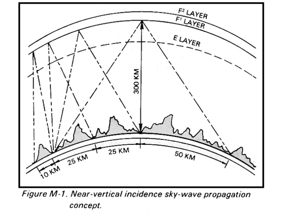
High Angle Radiation NVIS or Near Vertical Incidence Sky-wave

74
NVIS Radio Waves that take off at very high angles are reflected straight back to Earth.

75
NVIS Like squirting a hose at the ceiling, this technique allows you to blanket your signals over a significant area close to your station.

77
NVIS This technique will provide reliable communications within a 200 to 350 mile radius. Frequency choice for NVIS is typically 40m during the day and 80m at night Unlike the ground wave, NVIS signals are not affected by terrain.

78
The Gray Line The transition area between daylight and darkness is called “the gray line.” This area offers some unique and special propagation to the radio operator.

79
The gray line or terminator is a transition region between daylight and darkness. One side of the Earth is coming into sunrise, and the other is just past sunset.

80
Building a Station Building an effective HF station is very simple.

81
Building a Station There are basically three main components involved:
An HF transceiver; An antenna system. (The antenna system consists of the radiator, feed-line and matching network; Good and Proper Grounding.

82
Building a Station Accessories
As you become more involved in HF activity you will find that there are certain accessories that will make building and operating your station a little easier.

83
Transceivers What is a Transceiver?
A transceiver is a single unit that acts as transmitter and receiver.

84
Transceivers There are many transceivers on the market today.
For our discussion we will limit ourselves to the classic 100 watt, all mode type of transceivers.

85
Transceivers All of the commercially manufactured transceivers on the market today are state of the art and can provide good communications worldwide…

86
Transceivers …some of the better units offer more sophisticated circuits designed to increase the receiver’s ability to hear and select weak signals.

87
Transceivers You do get what you pay for. Commercial manufacturers tend to offer units in good, better, or best categories. These can range from a few hundred dollars to several thousand dollars.

88
Transceivers There are a lot of good values to be had in the used equipment market. There are also a lot of good hams that get had in the used equipment and ham fest markets!!

89
Transceivers It is a great idea to consult a more experienced ham here in our club to assist you with selecting a used piece of gear. Feel free to ask, that’s part of what being in this club is about. If that person can’t help, they will find someone else in the club who can.

90
Transceivers Whichever transceiver you choose, you can be assured of many years of operating pleasure from your investment.

91
A Word About “Classic” Radios.
You will often hear hams talk about old classics and rigs that they used back in the day. (Some are often referred to as “Boat Anchors.”)
")
92
A Word About “Classic” Radios.
Classic radios are like classic cars.

93
A Word About “Classic” Radios.
They’re nice to look at, and can be fun to tinker with.

94
A Word About “Classic” Radios.
It’s a thrill take them out for a spin and show them off once in a while.

95
A Word About “Classic” Radios.
However; for your daily use, you may want to have something that is more modern and requires less maintenance.

96
A Word About “Classic” Radios.
Unless you are very talented and have a source for extinct components it’s a good idea to avoid these “boat anchors” as a first or primary radio.

97
Transceivers What makes a good radio?
Scanning, memories and other “bells & whistles” are not the important features that make a good HF rig.

98
Transceivers What makes a good radio?
The receiver’s ability to hear weak signals and separate the incoming signals are what makes a good HF rig.

99
Transceivers sensitivity (ability to hear signals) and
What makes a good radio? The key points to look at when selecting a transceiver are: sensitivity (ability to hear signals) and selectivity (ability to distinguish signals)
 and. selectivity (ability to distinguish signals)")
100
Remember, you can’t work them if you can’t hear them.
Transceivers What makes a good radio? Remember, you can’t work them if you can’t hear them.

101
Common Controls Found On Amateur Radio Transceivers.

102
Multi function meter shows information at a glance
Use the meter like the speedometer in your car; don’t stare at it, but glance at it, making sure all things are proper.

103
Meter Functions 10 over S9. S9 + 20, etc.
“S” or Signal strength – This indicates the relative strength of a received signal on a scale of 1 through 9. Strong signals are reported as dB over S9. 10 over S9. S9 + 20, etc.

104
Reading The S Meter The receive signal on the meter here is 32 dB over S-9 or simply said, “30 over.”

105
Meter Functions RF POWER – This shows how much power the transmitter is generating to the antenna.

106
Meter Functions SWR – This shows the Standing Wave Ratio of the antenna, or how much power is being reflected back to the radio. 1:1 is excellent!

107
Meter Functions ALC – This shows the condition of the Automatic Limiting Control circuitry. You want to make sure that you are not over-driving your transmitter. A good reading is when the peaks top the scale and stay within the range marked on the meter scale.

108
What Are All Those Knobs?

109
VFO – Variable Frequency Oscillator
VFO – Variable Frequency Oscillator. This is the main tuning knob used to tune the frequency. This tunes your transmit and receive frequencies that are shown on the MAIN DISPLAY.

110
Controls AF (gain) – Audio Frequency gain. This is the “VOLUME” control for the receiver.
 – Audio Frequency gain. This is the VOLUME control for the receiver.")
111
Controls RF GAIN – This allows you to adjust the gain of the receiver’s Radio Frequency amplifier circuits. It allows you to make the receiver less sensitive so you can attenuate very strong signals.

112
Controls By changing the gain in the receiver circuits you can lower the noise floor and effectively improve the signal to noise ratio, thus improving your ability to hear weaker signals.

113
Controls When you adjust the RF GAIN it is normal to see the “S” METER rise.

114
Controls MIC GAIN- This controls the amplification of the microphone in voice modes. It is best to adjust this for a good “in range” reading on the ALC meter.

115
Controls MODE – This allows you to choose the mode of operation for your transceiver. CW – Continuous Wave (Morse code) USB – Upper Sideband LSB – Lower Sideband RTTY – Radio Teletype

116
Controls RIT – This stands for Receive Independent Tuning. It is used to fine tune a station you are listening to without changing your transmit frequency.

117
Controls XIT- Transmit Independent Tuning is similar to RIT but it only adjusts your transmit frequency.

118
Controls RF PWR – This adjusts the amount of transmitter output power.

119
Controls IF SHIFT - This shifts the center of the receiver’s pass band. Pronounced “eye eff”, it stands for Intermediate Frequency

120
Controls Shifting the IF allows you to avoid a signal that is close to yours by not letting it in the “window” of the receiver’s pass band.

121
Controls NOTCH – This is another good filter for reducing nearby interference. Unlike a window, it acts like a blind and blocks the signal that is in your window.

122
Antennas

123
Antennas Now calm down. You don’t need an antenna farm like the one shown at N5AU to have fun on HF.

124
Antennas When we talk about our antennas we are actually talking about an antenna system.

125
BIG NOTE * *An entire program can be had just on the discussion of antennas. Consideration should be given to safety and the type of operating that is being done, as well as spouse appeal. (End of Big Note.)
")
126
Antennas An antenna system consists of: The antenna or radiator
The feed-line The matching network or tuner (optional)
")
127
SWR A low SWR reading is not an indicator of an effective antenna system!!!!! Click your heels and say this three times.

128
SWR (There is only ONE) Think of a dummy load; it has a low SWR but it is NOT an effective antenna. Dummy loads are not designed to radiate!

129
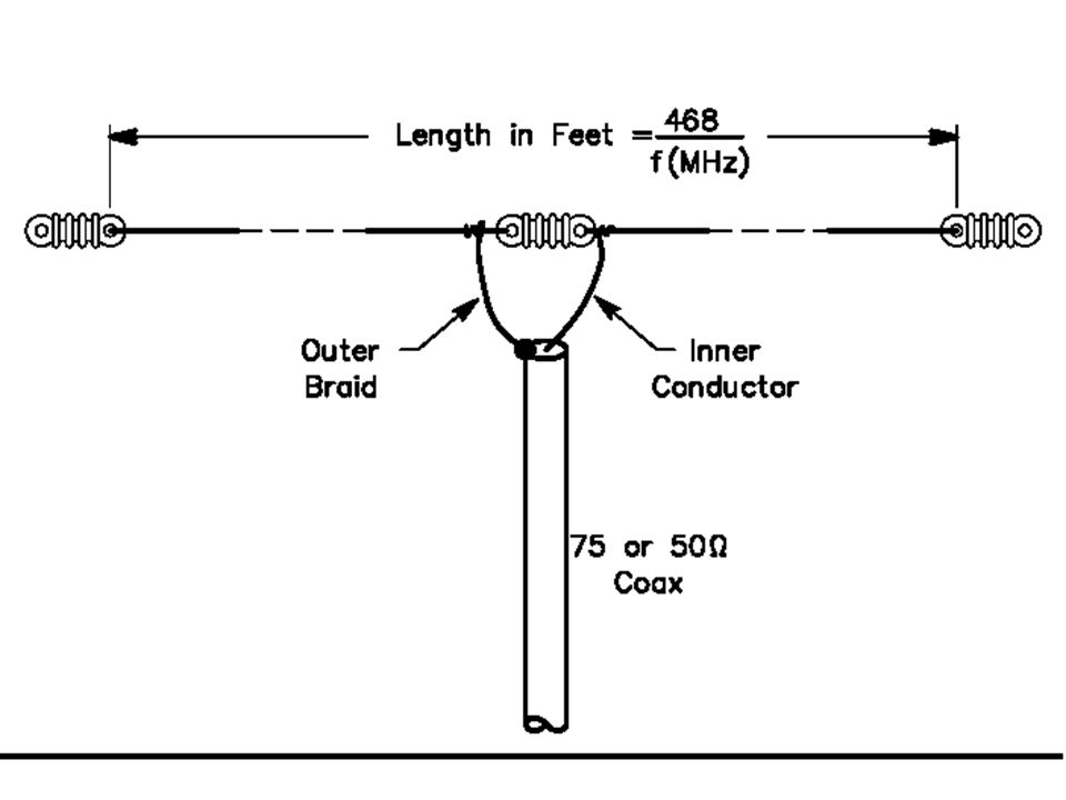
Antennas The dipole is the simplest antenna that any amateur can use on HF. Either fed with coax or ladder line, dipoles are cheap and easy to build and install.

130
Antennas A dipole fed with ladder line can be made to operate effectively on more than one band when using a good matching network.

131
Antennas A dipole can be made for a single band. The total length of the antenna can be calculated by using the formula: 468 ÷ freq (MHz) * Velocity Factor = length in feet of a half wave dipole.
 * Velocity Factor = length in feet of a half wave dipole.")
132
Antennas Each side, or leg, of the dipole is going to be one half of the total length. (Traditionally) Fed with 50 ohm coax, this antenna will be resonant on the single band that it was cut for.

133
The Dipole Radiator, Feedline and matching network
468 f (MHz) Feedline The Dipole Radiator, Feedline and matching network matching network
 Feedline. The Dipole Radiator, Feedline and matching network. matching network.")
136
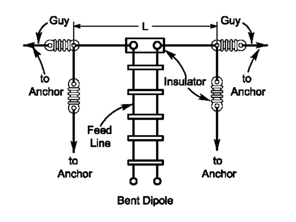
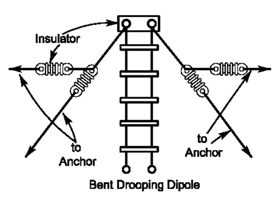
Antennas It is not necessary to install dipoles in a horizontal straight line.

137
Antennas Configurations include bent, drooping, inverted V and sloper.

139
“Inverted V”

141
Sloper

142
Antennas The tri-band Yagi or beam antenna is popular among a lot of HF operators. Even a modest 3 element model at heights as low as 40 ft can greatly improve your signal.

143
Antennas Many hams have earned their DXCC award using a small tri-band beam and 100 watts of power.

144
Three Element Tri-band Yagi

145
Antennas Vertical Antennas
It is recommended that you read about vertical antennas in the ARRL Antenna Book before installing one.

146
Antennas Many hams new to HF can become disappointed by vertical antennas because they don’t understand how they work or listen to myths about them.

147
Vertical antennas are excellent low angle radiators.
Ground mounted verticals often require an extensive radial system. Elevated mono-band verticals only require 4 radials to be effective.

148
Antennas Vertical antennas are excellent low angle radiators and can be good for DX’ing. A lot of “big gun” stations have verticals in their arsenal of antennas.

149
Antennas Large antenna arrays are extremely effective. (AM broadcast stations) The down side is that they require a lot of space, they’re expensive and they require periodic maintenance and safety inspections.

150
Antennas W1AW One of the towers at ARRL Headquarters. This 120 foot tower stands well above the local tree line and has lots of aluminum on it.

151
Antennas As you become a more experienced operator you will modify and improve your antenna farm. The most important thing now is to get a wire up and start having some fun.

152
Matching Networks The terms antenna tuner, match box, Transmatch and antenna coupler, are all synonyms for a matching network.

153
Matching Networks A matching network is a combination of inductance and capacitance used to cancel out unwanted reactance, to better couple the transmitter power to the antenna and feed-line.

154
Matching Networks Most modern transceivers have built in antenna tuners or matching networks that will match the transmitter section to the antenna and feed-line.

155
Matching Networks Think of the matching network like the transmission in a car.

156
Matching Networks While it is possible to connect the drive wheel directly to the engine, you will achieve a much more efficient transfer of power by using a transmission.

157
Matching Networks The matching network provides an efficient transfer of power from the transceiver to the antenna and feed-line.

158
Matching Networks However; the use of a matching network to achieve low SWR, can not make a poor antenna radiate any better.

159
Matching Networks The most common matching networks are the T- network, the Pi-network and the L-network.

160
L-Network

161
Pi-Network

162
T-Network

163
Feed-line The line that connects the antenna to the radio is called the feed-line.

164
Feed-line For the purpose of this demonstration we will only mention 50 ohm coax (unbalanced) and balanced ladderline or twin lead.
 and balanced ladderline or twin lead.")
165
Feed-line Most hams use 50 ohm coax to feed their antennas. It is easy to use and requires no special handling to bring it into the shack.

166
Feed-line Because of the 50 ohm impedance of the coax it matches the output of all modern transceivers.

167
Feed-line In addition to matching the transceiver’s output, the 50 ohm coax also closely matches the feed point impedance of a resonant dipole.

168
Feed-line Twin lead or ladderline can be used on mono or multi-band antennas. Because it is balanced, it has no feed-line loss!

169
Feed-line When used with a good tuner, a dipole fed with ladderline can be a very effective all band antenna. Also know as a “Doublet.”

170
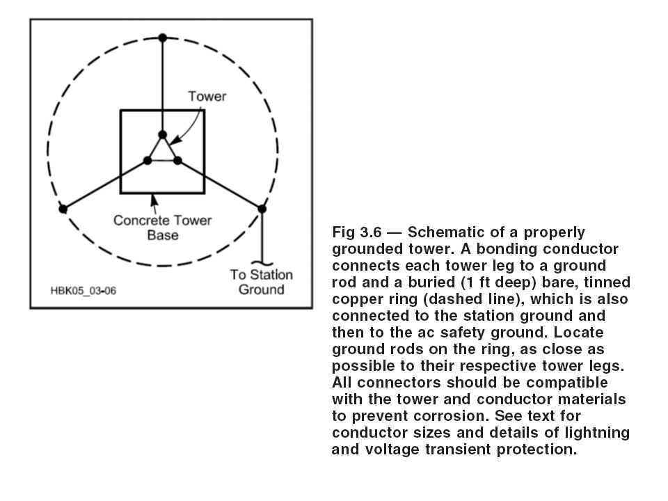
Grounding For lightning safety, to prevent interference, lower man-made noise, and increase antenna radiation efficiency, your station should be well grounded.

171
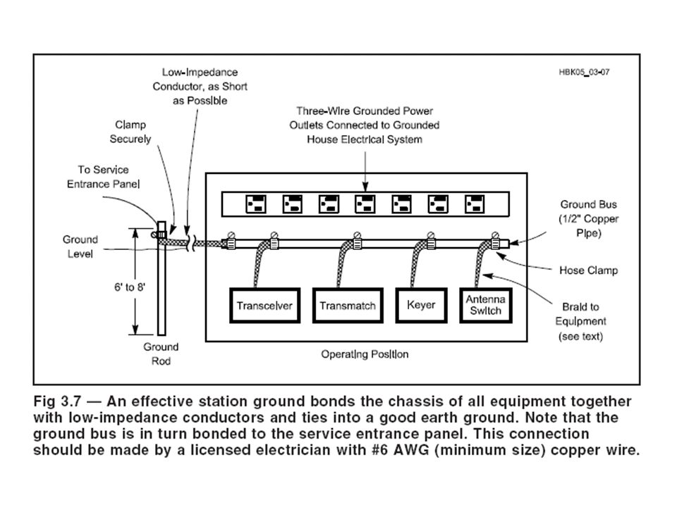
Grounding A good general statement is to have an earth ground using an 8 foot ground rod as close to the equipment as possible.

172
Grounding NEVER connect a ground to a gas pipe.
Avoid grounding to water pipes. NEVER connect a ground to a gas pipe.

173
Grounding If you add a ground rod, always bond it to the existing house ground!

174
Grounding All equipment should be grounded to a common point and then connected to the ground rod. DO NOT “daisy chain” or ground equipment to each other.

176
Grounding All antennas and antenna support structures (masts and towers) must be grounded. Feed-line should be grounded at the entry point to your shack.

178
Grounding All ground leads should be as short as possible and made with heavy gauge wire or wide copper strap.

179
Grounding Grounding should be checked yearly. Clean up corrosion at connections, make sure your copper has not been eaten away or stolen!

180
Grounding Please refer to the ARRL handbook for additional information on station grounding.

181
Safety Electrical Safety RF Safety Physical Safety

182
RF Safety As a licensed Amateur Radio operator you are required to know about RF exposure.

183
RF Safety Most 100 watt stations will not have any difficulty in meeting FCC exposure requirements.

184
RF Safety However, it is your responsibility to verify proper installation and operation of your station equipment, feed-line, antennas and grounding.

185
Or in the ARRL publication “RF Exposure and You” by Ed Hare, W1RFI
RF Safety Complete information about RF safety can be found on the ARRL website Or in the ARRL publication “RF Exposure and You” by Ed Hare, W1RFI

186
Physical Safety NEVER attempt to erect antennas near powerlines. You can easily be killed!

187
Physical Safety Keep all ladders on solid surfaces.
Always use safety equipment when climbing towers or roofs. Keep all ladders on solid surfaces.

188
Physical Safety Don’t work alone. It is a good idea to have a helper when trying to hang wires or climb towers.

189
Get On The Air Experienced HF operators in your local club will be able to advise you as you build your station.

190
Get On The Air DX and contesting clubs are good sources of information for HF operating.

191
Contests & Operating Events
Get On The Air Contests & Operating Events Participation in operating events will improve your skills and enhance your operating pleasure.

192
Get On The Air These events also provide opportunities to find ways to improve your station.

193
Get On The Air Awards There are many awards available for the HF operator to earn.

194
Get On The Air Awards The most coveted is the DX Century Club or DXCC, awarded for making contact with 100 countries.

196
Get On The Air Awards There are many other awards including the Worked All States (WAS) award for contacts with all 50 U.S States.
 award for contacts with all 50 U.S States.")
198
Get On The Air Choosing the band or mode of operation is up to you.
Listen for activity on all the bands; 40m – 10m during the day, 160m, 80m & 40m at night.

199
Get On The Air Now that you have the basics of HF operating, it’s time to get on the air and start having fun.

200
Publications ARRL License Manuals
201
Morse Code Study Materials
202
Publications ARRL Antenna Book

203
Publications The Complete DX'er by Bob Locher, W9KNI

204
Publications RF Exposure and You By Ed Hare, W1RFI

205
Club Contacts David Rudd – AI4JI ai4ji@comcast.net 678-462-4501
Satellite Bob – AG4BR

Similar presentations


 Radio ??. It’s a hobby, a technical hobby with a large number of different activities within it. It contains a certain element.>")


 2008 Gary C. Sutcliffe.>")


