Download presentation
Presentation is loading. Please wait.

1
Authored by John W. Desmarais 18-Dec-1999
Updated by Brockman 01-Jun-2003 Modified by Lt Colonel Fred Blundell TX-129 Fort Worth Senior Squadron For Local Training Rev Jan-2014

2
This Training Slide Show is a project undertaken by Lt Colonel Fred Blundell of the TX-129 Fort Worth Senior Squadron, Fort Worth, TX for local use to assist those CAP Members interested in advancing their skills. The information contained herein is for CAP Member’s personal use and is not intended to replace or be a substitute for any of the CAP National Training Programs. Users should review the presentation’s Revision Number at the end of each file name to ensure that they have the most current publication.

3
What are your responsibilities?
Team Leaders are responsible for knowing the ins and outs of the maps of their area Team members only know basic field work normally

4
What are maps? A 2 dimensional representation of a 3 dimensional area.
A tool A universal reference that can aid teams in coordination.

5
Topographic Map

6
Longitude

7
Latitude

8
Latitude and Longitude Examples
When reporting a position, give latitude first and then longitude

9
Magnetic Variation and the Declination Diagram
Compasses are affected by iron ore deposits throughout the earth, causing them not to point at true north, but at magnetic north instead This variation is known, and maps show the corrections to be made in the form of the declination diagram

10
Lines of Magnetic Variation

11
Sometimes the G-M angle is so little you won’t have to worry about it

12
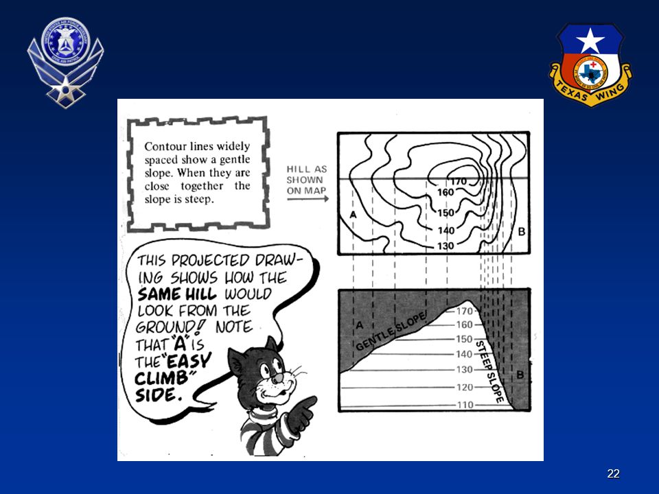
Declination Diagrams The difference in degrees for every map between grid north and magnetic north is shown at the bottom of the map.

13
Map Scale

16
Figuring Distance Suppose you want to find the distance between point A and point B around a curve in the road Take a piece of paper and put a tic mark on it. Place the tic mark at point A. Align the paper with the road edge until you come to the first curve in the road, make another mark on the paper and the map, and then pivot the paper so it continues to follow the road edge. Keep repeating until you reach point B. Always follow the road edge with your paper

18
Sample Map Symbols

19
Map Symbols (Continued)
")
20
Map Symbols (Continued)
")
21
The 3 Dimensional Model

25
Terrain Features (Continued)
")
26
Terrain Features (Continued)
")
28
Map Orientation A map can be oriented by terrain association when a compass is not available or when the user has to make many quick references as he moves across country Using this method requires careful examination of the map and the ground, and the user must know his approximate location.

29
Using your Map with your Compass
Field to Map Map to Field Triangulation Aiming Off The Polar Plot

30
Field to Map

31
Field to Map (Continued)
")
32
Field to Map (Continued)
")
33
Map to Field Orient your map to north and place your compass on the map with the edge (as shown) along the desired line of travel.
 along the desired line of travel.")
34
Map to Field (Continued)
Turn the compass Dial until “N” points to the North on your map. Your direction in degrees is read at the Index Line on the Dial.

35
Map to Field (Continued)
Remove the compass from the map and hold it level, so the Magnetic Needle is free to turn. Turn your body until the red end of the Needle aligns with the Orienting Arrow and “N” on the Dial. Using the Direction of Travel Arrow, sight a distant landmark and move to it. Repeat this process until you reach your destination.

36
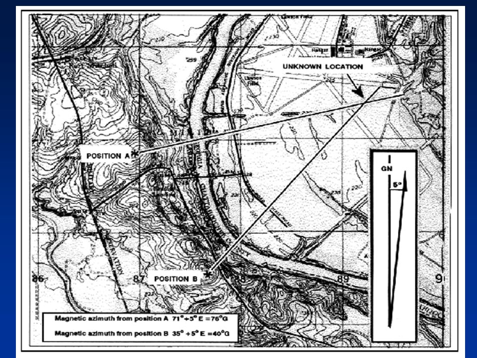
Triangulation Suppose you want to know the location of a certain object which you can see in the distance but is not on your map. First shoot the azimuth to the object you can see from your position. Draw a line on your map from your location out along the grid azimuth. The location of the object is somewhere on that line - but where?

37
Triangulation (Continued)
To find out- move yourself to a different location where you can still observe the object and shoot an azimuth to it.

38
Triangulation (Continued)
Convert the azimuth from magnetic to grid and draw it on the map. The object is where the lines intersect. You can also triangulate ELT signals by taking azimuths from DF signals to estimate the location of an ELT.

39
Triangulation (Continued)
By reversing the azimuths- you can triangulate back from objects to assist in finding your location on a map.

40
Triangulation (Continued)
")
41
Triangulation (Continued)
")
42
Triangulation (Continued)
")
44
Aiming Off Sometimes while heading for a target along a road, stream, ridge, or other landmark, it is better to plot an azimuth to the left or right of the target instead of directly towards it. Because of normal drift from terrain or compass variation it is easy to be slightly off from a small target. By aiming left (or right) you know what direction to begin searching for your target when you hit the stream- search to the right.
 you know what direction to begin searching for your target when you hit the stream- search to the right.")
45
Aiming Off (Continued)
")
46
Polar Plot A method of plotting or locating an unknown position from a known point by giving a direction and a distance along that direction line is called a polar plot Three elements must be present when using polar coordinates 1. Present known location on the map 2. Azimuth (grid or magnetic) 3. Distance (normally yards or meters)
 3. Distance (normally yards or meters)")
48
Orientating a Map The first step for a navigator in the field is orienting the map. A map is oriented when it is in a horizontal position with its north and south corresponding to the north and south on the ground. When orienting a map with a compass, remember that the compass measures magnetic azimuths. Since the magnetic arrow points to magnetic north, pay special attention to the declination diagram. (1) First Technique. Determine the direction of the declination and its value from the declination diagram. (a) With the map in a horizontal position, take the straightedge on the left side of the compass and place it alongside the north-south grid line with the cover of the compass pointing toward the top of the map. This procedure places the fixed black index line of the compass parallel to north-south grid lines of the map. (b) Keeping the compass aligned as directed above, rotate the map and compass together until the magnetic arrow is below the fixed black index line on the compass. At this time, the map is close to being oriented. (c) Rotate the map and compass in the direction of the declination diagram. (d) If the magnetic north arrow on the map is to the left of the grid north, check the compass reading to see if it equals the G-M angle given in the declination diagram. The map is then oriented
 First Technique. Determine the direction of the declination and its value from the declination diagram. (a) With the map in a horizontal position, take the straightedge on the left side of the compass and place it alongside the north-south grid line with the cover of the compass pointing toward the top of the map. This procedure places the fixed black index line of the compass parallel to north-south grid lines of the map. (b) Keeping the compass aligned as directed above, rotate the map and compass together until the magnetic arrow is below the fixed black index line on the compass. At this time, the map is close to being oriented. (c) Rotate the map and compass in the direction of the declination diagram. (d) If the magnetic north arrow on the map is to the left of the grid north, check the compass reading to see if it equals the G-M angle given in the declination diagram. The map is then oriented.")
49
Orientation with a Compass
(2) Second Technique. Determine the direction of the declination and its value from the declination diagram. (a) Using any north-south grid line on the map as a base, draw a magnetic azimuth equal to the G-M angle given in the declination diagram with the protractor. (b) If the declination is easterly (right), the drawn line is equal to the value of the G-M angle. Then align the straightedge, which is on the left side of the compass, alongside the drawn line on the map. Rotate the map and compass until the magnetic arrow of the compass is below the fixed black index line. The map is now oriented
 Second Technique. Determine the direction of the declination and its value from the declination diagram. (a) Using any north-south grid line on the map as a base, draw a magnetic azimuth equal to the G-M angle given in the declination diagram with the protractor. (b) If the declination is easterly (right), the drawn line is equal to the value of the G-M angle. Then align the straightedge, which is on the left side of the compass, alongside the drawn line on the map. Rotate the map and compass until the magnetic arrow of the compass is below the fixed black index line. The map is now oriented.")
50
Orientate a Map to Ground by Terrain Association
A map is orientated when it is in a horizontal position with its north and south corresponding to the north and south on the ground Look at the map and find two terrain features that can also be seen looking around (hilltops, saddles, ridges, towers, etc.)
")
51
Orientate a Map to Ground by Terrain Association (Continued)
By aligning terrain features on the map with the same terrain features on the ground- the map is orientated Check orientations obtained by this method to keep from having it in the wrong direction (180 degrees out). This can be avoided by aligning two or more features.
. This can be avoided by aligning two or more features.")
52
Vehicle Navigation The principles of land navigation while mounted are basically the same as while dismounted The major difference is the speed of travel. Walking between two points may take one hour, but riding the same distance may only take 15 minutes To be effective at mounted land navigation, the travel speed must be considered

53
Navigator The duties of a navigator are so important and exacting that he/she should not be given any other duties. The leader should never try to be the navigator, since his normal responsibilities are heavy, and one or the other job would suffer. The navigator must gather all the equipment that will help him/her perform his job (maps, pencils, and so forth). He/she must do this before the mission starts.
. He/she must do this before the mission starts.")
54
Navigator (Continued)
During movement, the navigator must make sure that the correct direction and distance are recorded and followed. Grid coordinates or road locations must be recorded and plotted The TL normally selects the route that he desires to use. The navigator is responsible for following that route

55
References FM 3-25.26 Land Navigation
GTA –013 How To Avoid Getting Lost Silva Easy as 1-2-3 NGSAR Manual

56
QUESTIONS? ALWAYS THINK SAFETY!

Similar presentations