Download presentation
Presentation is loading. Please wait.

1
EMBEDDED SOFTWARE (COMPUTER ON CHIP) ATMEL AT80S51 PC12
 ATMEL AT80S51 PC12")
2
EMBEDDED SOFTWARE Port 3 Port 1 ORG 00H MainLoop: SetB P1.2 ACall Delay Clr P1.2 SJMP MainLoop ; Delay 400Machine Cycles Delay: mov R1, #200 Again: DJNZ R1, Again RET END COMPUTER ON CHIP Port 2 Port 0 Time

3
What is a µc? µC is a Computer on chip

4
What is a µc? µC is a Computer on chip

5
COMPUTER SYSTEM Computer System comprises of:-
Central Processing Unit - for processing Keyboard, Mouse - for inputs Monitor, Printer - for outputs 5

6
Let us Assemble this Computer
Keyboard CPU Monitor Keyboard CPU Monitor

7
Let us Assemble this Computer
Keyboard CPU Monitor Monitor Keyboard CPU Control Sensor

8
COMPONENTS ON THE CPU Motherboard Microprocessor Memory. ROM RAM
Ports. Input ports Output Ports Drives: FDD, HDD, CDR

9
COMPONENTS ON THE CPU Motherboard Microprocessor Memory. ROM RAM
Ports. Input ports Output Ports Drives: FDD, HDD, CDR Yes On MB Large 512MB Ports. On Ports No On Chip 2,4,..KB 128, . .Byte Ports. No drive

10
APPLICATIONS OF SOFTWARE continued . . .

11
4. PRODUCT LINE SOFTWARE Inventory control products. Word processing
Spread sheets Computer graphics Multimedia Entertainment Database management Personal and business financial applications.

12
5. WEB APPLICATIONS Simple:-
Little more than a set of linked hypertext files that present information using text and limited graphics. For E-commerce(Buying and selling) and B2B (Business to Business) Standalone features, computing functions and content to end user Integrated with corporate (being a corporation, having a legal existence) databases and business applications.
 and B2B (Business to Business) Standalone features, computing functions and content to end user. Integrated with corporate (being a corporation, having a legal existence) databases and business applications.")
13
6. ARTIFICIAL INTELLIGENCE
AI (Artificial Intelligence) software makes use of nonnumerical algorithms to solve complex problems that are not amenable to computation or straightforward analysis. Applications in this area include:- Robotics Expert systems Pattern recognition (image and voice) Artificial neural networks Theorem proving Game playing
 software makes use of nonnumerical algorithms to solve complex problems that are not amenable to computation or straightforward analysis. Applications in this area include:- Robotics. Expert systems. Pattern recognition (image and voice) Artificial neural networks. Theorem proving. Game playing.")
14
ARTIFICIAL NEURAL NETWORKS
Traditionally, the term neural network had been used to refer to a network or circuit of biological neurons. The modern usage of the term often refers to artificial neural networks, which are composed of artificial neurons or nodes. Thus the term has two distinct usages: Biological neural networks are made up of real biological neurons that are connected or functionally related in the peripheral nervous system or the central nervous system. In the field of neuroscience, they are often identified as groups of neurons that perform a specific physiological function in laboratory analysis. Artificial neural networks are made up of interconnecting artificial neurons (programming constructs that mimic the properties of biological neurons). Artificial neural networks may either be used to gain an understanding of biological neural networks, or for solving artificial intelligence problems without necessarily creating a model of a real biological system. The real, biological nervous system is highly complex and includes some features that may seem superfluous based on an understanding of artificial networks.
. Artificial neural networks may either be used to gain an understanding of biological neural networks, or for solving artificial intelligence problems without necessarily creating a model of a real biological system. The real, biological nervous system is highly complex and includes some features that may seem superfluous based on an understanding of artificial networks.")
15
APPLICATIONS OF SOFTWARE
New Challenges:- Ubiquitous Computing. Ubiquitous means found everywhere; omnipresent The rapid growth of wireless networking may soon lead to true distributed computing. The challenge for SW engineers will be:- to develop systems and application software that will allow small devices, personal computers, and enterprise system to communicate across vast networks. (Enterprise: an organization created for business ventures, a business firm, a company. Enterprise system: A system that supports enterprise-wide or cross- functional requirements, rather than a single department or group within the organization)
")
16
DISTRIBUTED COMPUTING
Distributed computing deals with:- hardware and software systems containing more than one processing element or storage element, concurrent processes, or multiple programs, running under a loosely or tightly controlled regime.

17
DISTRIBUTED COMPUTING
In distributed computing:- a program is split up into parts that run simultaneously on multiple computers communicating over a network. Distributed computing is a form of parallel computing, but parallel computing is most commonly used to describe program parts running simultaneously on multiple processors in the same computer. Both types of processing (i.e. Distributed and Parallel) require dividing a program into parts that can run simultaneously, but distributed programs often must deal with:- heterogeneous environments, network links of varying latencies (the delay before a transfer of data begins following an instruction for its transfer), and unpredictable failures in the network or the computers.
 require dividing a program into parts that can run simultaneously, but distributed programs often must deal with:- heterogeneous environments, network links of varying latencies (the delay before a transfer of data begins following an instruction for its transfer), and unpredictable failures in the network or the computers.")
18
APPLICATIONS OF SOFTWARE
New Challenges:- 2. Netsourcing. The World Wide Web is rapidly becoming a computing engine as well as content provider. The challenge for SW engineers is to architect simple (e.g. personal financial planning) and sophisticated applications that provide benefit to targeted end-user market worldwide. (The Web is one of the services available on the Internet. It lets you access millions of pages through a system of links; because it is 'world-wide,' it was originally called the World Wide Web or
 and sophisticated applications that provide benefit to targeted end-user market worldwide. (The Web is one of the services available on the Internet. It lets you access millions of pages through a system of links; because it is world-wide, it was originally called the World Wide Web or")
19
INTERNET Internet. The Internet is a:- worldwide, publicly accessible
series of interconnected computer networks that transmit data by packet switching using the standard Internet Protocol (IP) worldwide communications network originally developed by the US Department of Defense as a distributed system with no single point of failure.
 worldwide communications network. originally developed by the US Department of Defense as a distributed system with no single point of failure.")
20
TCP/IP Short for “Transmission Control Protocol and Internet Protocol”, two of the core protocols that make the internet work. TCP ensures that data is received in the order it is sent, and IP allows computers to identify each other across the internet using IP addresses.

21
APPLICATIONS OF SOFTWARE
New Challenges:- 3. Open Source. A growing trend that results in distribution of source code for system applications (e,g. operating systems, database, and development environment) so that customers can make local modifications. The challenge for software engineers is to build source code that is self descriptive, but, more importantly to develop techniques that will enable both customers and developers to know what changes have been made and how those changes manifest themselves within the software. 4. The “New Economy”. The challenge for SW engineers is to build applications that will facilitate:- Mass communication Mass product distribution
 so that customers can make local modifications. The challenge for software engineers is to build source code that is self descriptive, but, more importantly to develop techniques that will enable both customers and developers to know what changes have been made and how those changes manifest themselves within the software. 4. The New Economy . The challenge for SW engineers is to build applications that will facilitate:- Mass communication. Mass product distribution.")
22
APPLICATIONS OF SOFTWARE
Further details …

23
OTHER APPLICATIONS OF SOFTWARE
Real Time S/W Embedded S/W Edutainment S/W Communications S/W Utility S/W

24
FOURTH GENERATION TECHNIQUES*

25
FOURTH GENERATION TECHNIQUES*
The term fourth generation technique (4GT) encompasses a broad array of software tools that have one thing in common :- each enables the software engineer to specify some characteristics of software at a high level. The tool then automatically generates source code based on the developer's specification. The 4GT paradigm for Software Engineer focuses on the ability to specify software using:- specialized language forms or a graphic notation that describes the problems to be solved in terms that the customers can understand.
 encompasses a broad array of software tools that have one thing in common :- each enables the software engineer to specify some characteristics of software at a high level. The tool then automatically generates source code based on the developer s specification. The 4GT paradigm for Software Engineer focuses on the ability to specify software using:- specialized language forms or. a graphic notation that describes the problems to be solved in terms that the customers can understand.")
26
FOURTH GENERATION TECHNIQUES…
Currently, a software development environment that supports the 4GT paradigm includes some or all of the following tools:- non procedural languages for:- database query, report generation, data manipulation, screen interaction and definition, code generation ; high-level graphics capability ; spreadsheet capability and automated generation of HTML and similar languages used for web-site creation using advanced software tools. Initially, many of tools noted previously were available only for very specific application domains, but today 4GT environments have been extended to address most software application categories.

27
FOURTH GENERATION TECHNIQUES…
Like other paradigms, 4GT begins with a requirements gathering step. Ideally, the customer would describe requirements and these would be directly translated into an operational prototype. But this is unworkable. The customer may be unsure of what is required, may be ambiguous in specifying facts that are known, and may be unable or unwilling to specify information in a manner that a 4GT tool can consume. For this reason, the customer/ developer dialog described for other process models remains an essential part of the 4GT approach.

28
FOURTH GENERATION TECHNIQUES…
For small applications, it may be possible to move directly from the requirements gathering step to implementation using a non procedural fourth generation language (4GT) or a model composed of a network of graphical icons. However, for larger efforts, it is necessary to develop a design strategy for the system, even if a 4GT is to be used. The use of 4GT without design (for large projects) will cause difficulties like:- poor quality, poor maintainability, poor customer acceptance etc. that have been encountered when developing software using conventional approaches.
 or a model composed of a network of graphical icons. However, for larger efforts, it is necessary to develop a design strategy for the system, even if a 4GT is to be used. The use of 4GT without design (for large projects) will cause difficulties like:- poor quality, poor maintainability, poor customer acceptance etc. that have been encountered when developing software using conventional approaches.")
29
FOURTH GENERATION TECHNIQUES…
Implementation using a 4GL enables the software developer to represent desired results in a manner that leads to automatic generation of code to create those results. Obviously, a data structure with relevant information must exist and be readily accessible by the 4GL.

30
FOURTH GENERATION TECHNIQUES…
To transform a 4GT implementation into a product, the developer must:- conduct thorough testing, develop meaningful documentation, and perform all other solution integration activities that are required in other software engineering paradigms. In addition, the 4GT developed software must be built in a manner that enables maintenance to be performed expeditiously.

31
4GT: ADVANTAGES AND DISADVANTAGES…
Like all software engineering paradigms, the 4GT model has advantages and disadvantages. Proponents claim dramatic reduction in software development time and greatly improved productivity for people who built software. Opponents claim that current 4GT tools are not all that much easier to use than programming languages, that the resultant source code produced by such tools is "inefficient", and that the maintainability of large software systems developed using 4GT is open to question. There is some merit in the claims of both sides and it is possible to summarize the current state of 4GT approaches :-

32
SUMMARY OF THE CURRENT STATE OF 4GT APPROACHES
The use of 4GT is a viable approach for many different application areas. Coupled with computer-aided software engineering tools and code generators, 4GT offers a credible solution to many software problems. Data collected from companies that use 4GT indicate that the time required to produce software is greatly reduced for small and intermediate applications and that the amount of design and analysis for small applications is also reduced. However, the use of 4GT for large software development efforts demands as much or more analysis, design and testing to achieve substantial time savings that result from the elimination of coding.

33
FOURTH GENERATION TECHNIQUES MODEL (4 GT MODEL)…
Use tools to generate source code based on the specification Develop software at faster speed Tools Non Procedural languages for database query Report generation Data manipulation Screen interaction Code generation Graphics capability Spread sheet capability

34
OTHER MODELS There are a number of other models for software development like the:- Stepwise Refinement Model, Industrial and Military Standard Models, Assembly by Reuse, Application Generation, Continuous Transformation Models, Knowledge-Based Software Automation etc. However, most of these are refinements of the models that we have already discussed, with variations brought in to suit a particular system software or platforms or the nature of the industry.

35
CONCEPTS OF PROJECT MANAGEMENT*

36
CONCEPTS OF PROJECT MANAGEMENT
Despite the availability of various engineering paradigms and competent programmers, the years 1960 and early 1970's witnessed a major failure of many large software projects. The software:- was delivered late was unreliable cost several times the original estimates and often exhibited poor performance characteristics. These projects failed due to lack of proper project management.

37
CONCEPTS OF PROJECT MANAGEMENT…
1. Project Management primary deals with:- Organizing planning and scheduling of software projects. 2. The role of project management is very important because:- software development is always subject to budget and schedule constraints. 3. The software project manager's job is to ensure that the software project meets these constraints and delivers software in time.

38
CONCEPTS OF PROJECT MANAGEMENT…
1. Software project managers are responsible for:- planning and scheduling project development. 2. They supervise the work to ensure that it is carried out to the required standards. 3. They regularly monitor progress to check that the development process is on the right track i.e. on time and within budget. 4. Good management does not guarantee project success. However, bad management does lead to project failures.

39
CONCEPTS OF PROJECT MANAGEMENT…
5. The Software Project Management becomes all the more important and particularly difficult due to the following reasons:- S/W Product is Intangible (unable to be touched) There is no standard process New S/W projects are not similar to previous ones.
 There is no standard process. New S/W projects are not similar to previous ones.")
40
FOUR P’s IN PROJECT MANAGEMENT
People Product Process Project

41
CONCEPTS OF PROJECT MANAGEMENT (AS PER ROGER S PRESSMAN)
")
42
CONCEPTS OF ROJECT MANAGEMENT
Project management involves:- planning, monitoring, and control of the people, process, and events that occur as software evolves from a preliminary concept to an operational implementation.

43
CONCEPTS OF PROJECT MANAGEMENT
Who does it? 1. A software engineer manages his day- to-day activities:- planning, monitoring, and controlling technical tasks. 2. Project managers plan, monitor, and control the work of a team of software engineers. 3. Senior managers coordinate the interface between the business and the software professionals.

44
CONCEPTS OF ROJECT MANAGEMENT
Why is it important? Building computer software is a complex undertaking, particularly if it involves many people working over a relatively long time. That’s why software projects need to be managed.

45
CONCEPTS OF ROJECT MANAGEMENT
What are the steps? Understand the four P’s— people, product, process, and project. 1. People. People must be organized to perform software work effectively. 2. Product. Communication with the customer must occur so that product scope and requirements are understood.

46
CONCEPTS OF ROJECT MANAGEMENT
3. Process. A process must be selected that is appropriate for the people and the product. 4. Project. The project must be planned by estimating effort and calendar time to accomplish work tasks:- defining work products, establishing quality checkpoints, and establishing mechanisms to monitor and control work defined by the plan.

47
CONCEPTS OF ROJECT MANAGEMENT
What is the work product? A project plan is produced as management activities commence. The plan defines:- the process and tasks to be conducted, the people who will do the work, and the mechanisms for:- assessing risks, controlling change, and evaluating quality.

48
CONCEPTS OF ROJECT MANAGEMENT
How do I ensure that I’ve done it right? You’re never completely sure that the project plan is right until you’ve delivered a high- quality product on time and within budget. However, a project manager does it right when:- he encourages software people:- to work together as an effective team, focusing their attention on:- customer needs and product quality.

49
FOUR P’s IN PROJECT MANAGEMENT
1. People Senior Managers Project Managers Programmers Customers End users

50
FOUR P’s IN PROJECT MANAGEMENT…
1. People… 1. Senior Managers: They define the business issues that have significant influence on the project. 2. Project Managers: They plan, motivate, organise and control the programmers who do S/W work. 3. Programmers: They use technical skills to develop a product. 4. Customers: They are generally heads of the organisations who specify the needs of the organisation for automation. 5. End Users: They would be generally clerks, operators etc. who actually use the S/W. Some functions of the S/W are also used by people higher in chain of command.

51
FOUR P’s IN PROJECT MANAGEMENT
Project Manager. Motivation Organisation Innovation Problem Solving Managerial Capabilities Leadership Skills Influence and Team Building

52
FOUR P’s IN PROJECT MANAGEMENT
Programmers/The Software Team. 1. Democratic or Egoless Team. 2. Controlled Centralised or Chief Programmer Team 3. Controlled Decentralised Team

53
FOUR P’s IN PROJECT MANAGEMENT
1. Democratic or Egoless Team.

54
FOUR P’s IN PROJECT MANAGEMENT
Programmers/ The Software Team… 2. Controlled Centralised or Chief Programmer Team

55
FOUR P’s IN PROJECT MANAGEMENT
Programmers/The Software Team. 3. Controlled Decentralised Team. This structure tries to combine the strengths of democratic and controlled centralised teams. It has a Project Leader who has a group of senior programmers under him. Under each senior programmer is a group of junior programmers.

56
FOUR P’s IN PROJECT MANAGEMENT
Programmers/ The Software Team. 1. Democratic or Egoless Team. Upto 10 programmers Goals set by consensus Inputs from every member are taken for major decisions Group leadership rotates among team members Not suitable for:- Complex tasks Tasks with time constraints, Results in inefficiency

57
FOUR P’s IN PROJECT MANAGEMENT
Programmers/ The Software Team. 2. Controlled Centralised or Chief Programmer Team. Follows a hierarchy There is a chief programmer with:- Backup programmer Program librarian for maintaining documentation and other communication related work Reduced inter-personal communication Suitable for projects with:- Simple solutions Strict deadlines Not suitable for difficult tasks where multiple inputs are useful.

58
Programmers/The Software Team.
3. Controlled Decentralised Team Tries to combine the strengths of democratic and controlled centralised teams. Consists of:- Project leader with senior programmers under him. Under each senior programmer:- a group of junior programmers. This forms a democratic team Communication among different groups occurs through senior programmers of respective groups. Senior programmers also communicate with project leader Fewer communication paths than democratic but more than controlled centralised. Best for large projects that are straight forward. Not well suited for simple projects or research projects.

59
PROJECT FACTORS FOR PLANNING SOFTWARE TEAM
Difficulty of problem to be solved. Size of resultant program(s) in Lines of Code or Function Points. The time that the team will stay together. Degree to which the problem can be modularised. Required quality and reliability of the system to be built. Rigidity of delivery date. Degree of communication required for the project.
 in Lines of Code or Function Points. The time that the team will stay together. Degree to which the problem can be modularised. Required quality and reliability of the system to be built. Rigidity of delivery date. Degree of communication required for the project.")
60
FOUR P’s IN PROJECT MANAGEMENT
2. The Product. Software scope must be established and bounded at the very beginning. Problem Decomposition.

61
FOUR P’s IN PROJECT MANAGEMENT
3. The Process. Generic phases that characterise the software process applicable to all S/W:- Definition Development Support Select suitable process model from:- Linear/Life cycle Prototyping Spiral 4GT Model Define project plan based on common process framework activities

62
FOUR P’s IN PROJECT MANAGEMENT
4. The Project. What can go wrong? How to do it right? Problem Indicators:- Customer’s needs Scope Changes managed poorly Chosen technology changes Business needs change Deadlines are unrealistic Users are resistant Lacking of appropriate skills

63
FOUR P’s IN PROJECT MANAGEMENT
The Project. How to do it right? Start on the right foot Maintain momentum Track progress Keep it simple Conduct a post-mortem analysis

64
PROJECT MANAGEMENT ACTIVITIES
1. Measurement and metrics 2. Management activities 3. Project planning 4. Scheduling 5. Tracking 6. Risk management These are umbrella activities

65
ROLE OF METRICS*

66
HOW TO CALULATE COST Cost is generally based on:- Utility Quantity
Quality Effort involved Degree of difficulty Ease of use Aesthetics

67
ROLE OF METRICS Metrics: A standard of measurement For example:-
Metrics for solids: Weight (kg, gm etc) Metrics for liquids: Litre, ml etc. Metrics for gases: Cubic meters, cc etc. Metrics for length: meter, cm etc.
 Metrics for liquids: Litre, ml etc. Metrics for gases: Cubic meters, cc etc. Metrics for length: meter, cm etc.")
68
ROLE OF METRICS… When you can measure what you are speaking about and express it in numbers, you know something about it; but when you cannot measure, when you cannot express it in numbers, your knowledge is of a meagre (deficient or inferior) and unsatisfactory kind:- it may be the beginning of knowledge, but you have scarcely, in your thoughts, advanced to the stage of a science Lord Kelvin
 and unsatisfactory kind:- it may be the beginning of knowledge, but you have scarcely, in your thoughts, advanced to the stage of a science. - Lord Kelvin.")
69
ROLE OF METRICS… What is metrics?
Software process and product metrics are quantitative measures (measure: size or quantity as ascertained or ascertainable by measuring) that enable software people:- to gain insight into the efficacy of the:- software process and the projects that are conducted using the process as a framework.
 that enable software people:- to gain insight into the efficacy of the:- software process and the. projects that are conducted. using the process as a framework.")
70
ROLE OF METRICS… What is metrics? …
Basic quality and productivity data are collected. These data are then:- analyzed, compared against past averages, and assessed to determine:- whether quality and productivity improvements have occurred. Metrics are also used to pinpoint problem areas so that remedies can be developed and the software process can be improved.

71
ROLE OF METRICS… Who does it? Software metrics are:-
analyzed and assessed by software managers. Measures are often collected by software engineers. (Meter rod is a measure, Measuring cloth is measurement. In case of Software: size, No. of functions, No. of Inputs, Outputs etc are measures.)
")
72
ROLE OF METRICS… Why is it important?
If you don’t measure, judgement can be based only on subjective evaluation. With measurement:- trends (either good or bad) can be spotted, better estimates can be made, and true improvement can be accomplished over time.
 can be spotted, better estimates can be made, and. true improvement can be accomplished over time.")
73
ROLE OF METRICS… What are the steps?
Begin by defining a limited set of:- process, project, and product measures that are easy to collect. These measures are often normalized (made equal to a particular value) using:- either size - or function-oriented metrics. The result is analyzed and compared to past averages for similar projects performed within the organization. Trends are assessed and conclusions are generated.
 using:- either size - or. function-oriented metrics. The result is analyzed and compared to past averages for similar projects performed within the organization. Trends are assessed and conclusions are generated.")
74
ROLE OF METRICS… What is the work product?
A set of software metrics that provide insight into the process and understanding of the project. (A software metric is a measure of some property of a piece of software or its specifications.)
")
75
ROLE OF METRICS… How do I ensure that I’ve done it right?
By applying a consistent, yet simple measurement scheme that is never to be used to assess, reward, or punish individual performance.

76
ROLE OF METRICS… The discipline of software engineering uses the concept of measurement, which enables software managers to:- determine the cost and effort devoted to project. assess software quality. understand and improve the software process. Predict, plan and control the software projects.

77
SOFTWARE MEASUREMENT…
Measures, Metrics and Indicators:- Measure: A measure provides a quantitative indication of the:- Extent Amount Dimension Capacity or Size of some attribute of a product or process. Measurement: is the act of determining a measure. Metric: The IEEE Standard Glossary[IEE93] defines Metric as “a quantitative measure of the degree to which a system, component, or process possesses a given attribute”

78
SOFTWARE MEASUREMENT…
There are two types of measurement:- Direct Measurement Indirect Measurement Entities of S/W Measurement. Three basic entities of S/W need to be measured and controlled:- Process Product Project

79
MEASUREMENT CRITERIA A successful measurement program should have the following key characteristics:- Objective and repeatable Timely Iterative Related to information needs

80
MEASUREMENT PROCESS Key stages:- Plan measurement Perform measurement
Evaluate measurement Provide Feedback

81
SOFTWARE METRICS A software metric is a quantifiable measure that could be used to measure different characteristics of a S/W or S/W development process. We need metrics to quantify the:- Development Operation and Maintenance of S/W

82
CLASSIFICATION OF S/W METRICS
S/W Product metrics S/W Process metrics S/W Project metrics

83
NEED FOR S/W METRICS S/W metrics are needed to answer the following:-
How long will it take to complete the project? How much will it cost to complete the project? How many persons and other resources would be required? What would be the likely maintenance cost? What and how to test for better quality? When can the S/W be released? How many errors will be discovered before delivering the product? How much effort would be required to make modifications?

84
SOME STANDARD PRODUCT METRICS
Size Metrics. Lines of Code LOC) Token Metrics Function Point and Extended Function Point Bang Metrics Code complexity metrics. Cyclomatic Complexity Information flow
 Token Metrics. Function Point and Extended Function Point. Bang Metrics. Code complexity metrics. Cyclomatic Complexity. Information flow.")
85
LOC Size Metrics. S/W size estimation is the process of predicting the size of a S/W product. Lines of Code (LOC). Simplest metric for estimating the effort and size of a computer program. Advantages. Simple to measure. Disadvantages. It is programming language dependent. Does not accommodate non-procedural languages. Poor S/W design may lead to excessive and unnecessary lines of code.
. Simplest metric for estimating the effort and size of a computer program. Advantages. Simple to measure. Disadvantages. It is programming language dependent. Does not accommodate non-procedural languages. Poor S/W design may lead to excessive and unnecessary lines of code.")
86
TOKEN METRICS Major drawback of LOC size measure:
It treats all the lines alike. In program there are some lines which are more difficult to code than others. One solution to this drawback may be to count the basic symbols used in a line instead of lines themselves. These basic symbols are called Tokens, which are classified as either operators or operands. For example: while, for, eof etc are all tokens.

87
TOKEN METRICS M.H. Halstead, proposed one of the token metric where the size of a program, which consists of the number of unique tokens can be defined in terms of : N1 = count of unique operators N2 = count of unique operands Length of program in terms of total number of tokens used is N = N1+N2 Where N1 = Count of total occurrences of operators N2 = Count of total occurrences of operands

88
TOKEN METRICS An operator, is any symbol or keyword in a program that specifies an action. Operators consist of:- symbols such as +, -, /, *, command names such as ‘while’, ‘for’ and special symbols such as braces, punctuation marks etc. An operand includes variables, constants and labels.

89
FUNCTION POINT METRICS

90
FUNCTION POINT Function Point(FP) was developed by Allan J. Albrecht in mid 1970’s. It was an attempt to overcome difficulties associated with LOC as a measure of S/W size, and to assist in developing a mechanism to predict effort associated with S/W development. FP basically is an objective and structured technique to measure S/W size by quantifying its functionality provided to the user based on the requirements and logical design. This technique breaks the system into smaller components so that they can be better understood and analysed.

91
FUNCTION POINT FP analysis, thus divides the system into five basic components namely:- 1. External Inputs 2. External Outputs 3. Queries 4. Logical Master File (Each logical master file (i.e., a logical grouping of data that may be one part of a large database or a separate file) is counted. Eg StudentMasterTable, FacultyMasterTable etc) 5. Interface File: It is a file or input-output data that is used by another application. These five components under FP analysis are rated as Simple, Average or Complex.
 is counted. Eg StudentMasterTable, FacultyMasterTable etc) 5. Interface File: It is a file or input-output data that is used by another application. These five components under FP analysis are rated as Simple, Average or Complex.")
92
FUNCTION POINT Type of Component Simple Average Complex Total
1. External Inputs ...x3 = … …x4=… …x6=… = 2. External Outputs ...x4 = … …x5=… …x7=… 3. Queries 4. Logical Master Files ...x7 = … …x10=… …x15=… 5. Interface File ...x5 = … Count Total Computing Count Total for FP

93
FUNCTION POINT To compute Function Point, the following relationship is used: FP = (Count Total) x [ x ∑(Fi)] The Fi (i = 1 to 14) are complexity adjustment values based on the response to the following questions:
![FUNCTION POINT To compute Function Point, the following relationship is used: FP = (Count Total) x [ x ∑(Fi)]](http://slideplayer.com/slide/2495860/9/images/93/FUNCTION+POINT+To+compute+Function+Point%2C+the+following+relationship+is+used%3A+FP+%3D+%28Count+Total%29+x+%5B+x+%E2%88%91%28Fi%29%5D.jpg "The Fi (i = 1 to 14) are complexity adjustment values based on the response to the following questions:")
94
Weightage Each of the following questions is answered using a scale that ranges from 0 (not important or applicable) to 5 (absolutely essential).
.")
95
FUNCTION POINT 1. Does the system require reliable backup and recovery? 2. Are data communications required? 3. Are there distributed processing functions? 4. Is performance critical? 5. Will the system run in an existing, heavily utilised operational environment? 6. Does the system require on-line data entry? 7. Does the on-line data entry require the input transcation to be built over multiple screens or operations?

96
FUNCTION POINT 8. Are the master files updated on-line? 9. Are the inputs, outputs, files or queries complex? 10. Is the internal processing complex? 11. Is the code designed to be reusable? 12. Are conversion and installation included in the design? 13. Is the system designed for multiple installations in different organisations? 14. Is the application designed to facilitate change and ease of use by the user?

97
FUNCTION POINT After the counts for each level of complexity for each type of component are entered, each counter is multiplied by the numerical rating. The rated values on each row are totalled. These totals are then summed down to arrive at the Count Total.

98
FUNCTION POINT Each of these questions is answered using a scale that ranges from 0 (not important or applicable) to 5 (absolutely essential). The constant values in Equation FP = (Count Total) x [ x ∑(Fi)] and the weighting factors that are applied to information domain counts are determined empirically.
 x [ x ∑(Fi)] and the weighting factors that are applied to information domain counts. are determined empirically.")
99
FUNCTION POINT Once function points have been calculated,
they are used in a manner analogous to LOC as a way to normalize measures for software productivity, quality, and other attributes: Errors per FP. Defects per FP. $ per FP. Pages of documentation per FP. FP per person-month.

100
FUNCTION POINT ADVANTAGES
Advantages of Function Point Function points can be used to size software applications accurately. They can be counted by different people at different times to obtain the same measure within a reasonable margin of error. FP are easily understood by non-technical user. This helps to communicate sizing information to a user or customer. FP can be used to determine whether a tool, a language, an environment is more productive when compared with others. FPs are language independent and can be computed early in a project. Due to these advantages, function points are becoming widely accepted as the standard metric for measuring software size.

101
QUALITY METRICS Correctness. Maintainability. Defects per KLOC
Defects are counted over a standard period of time Maintainability. Ease with which a program can be corrected if an error is encountered There is no direct method We measure it indirectly Mean Time To Change (MTTC)
")
102
QUALITY METRICS Integrity
This attribute measures a system’s ability to withstand attacks on:- Programs Data Documents To measure integrity, two additional attributes must be defined: Threat and Security

103
QUALITY METRICS Threat is the probability (which can be estimated or derived from empirical evidence) that an attack of a specific type will occur within a given time. Security is the probability (which can be estimated or derived from empirical evidence) that the attack of a specific type will be repelled. The integrity of a system can then be defined as Integrity = Summation[(1-threat) x (1-security)] (where threat and security are summed over each type of attack. i.e. attack on Programs, Data and Documents)
 that an attack of a specific type will occur within a given time. Security is the probability (which can be estimated or derived from empirical evidence) that the attack of a specific type will be repelled. The integrity of a system can then be defined as. Integrity = Summation[(1-threat) x (1-security)] (where threat and security are summed over each type of attack. i.e. attack on Programs, Data and Documents)")
104
QUALITY METRICS Usability.
Physical and or intellectual skill required to learn the system Time required to become moderately efficient The net increase in productivity measured when the system is used by someone who is moderately efficient A subjective assessment of users attitude towards the system.

105
PROJECT MANAGEMENT The application of knowledge, skills, tools and techniques to a broad range of activities in order to meet the requirements of a particular project.“ The process of directing and controlling a project from start to finish may be further divided into 5 basic phases: Project Conception and Initiation. An idea for a project will be carefully examined to determine whether or not it benefits the organization. During this phase, a decision making team will identify if the project can realistically be completed. 2. Project Definition and Planning. A project plan, project charter and/or project scope may be put in writing, outlining the work to be performed. During this phase, a team should prioritize the project, calculate a budget and schedule, and determine what resources are needed.

106
PROJECT MANAGEMENT 2. Project definition and planning.
A project plan, project charter and/or project scope may be put in writing, outlining the work to be performed. During this phase, a team should prioritize the project, calculate a budget and schedule, and determine what resources are needed. 3. Project launch or execution Resources' tasks are distributed and teams are informed of responsibilities. This is a good time to bring up important project related information. 4. Project performance and control Project managers will compare project status and progress to the actual plan, as resources perform the scheduled work. During this phase, project managers may need to adjust schedules or do what is necessary to keep the project on track.

107
PROJECT MANAGEMENT 5. Project close.
After project tasks are completed and the client has approved the outcome, an evaluation is necessary to highlight project success and/or learn from project history. Projects and project management processes vary from industry to industry; however, these are more traditional elements of a project. The overarching goal is typically to offer a product, change a process or to solve a problem in order to benefit the organization.

108
CONCEPTS OF PROJECT MANAGEMENT*
108 108
109
CONCEPTS OF PROJECT MANAGEMENT
Despite the availability of various engineering paradigms and competent programmers, the years 1960 and early 1970's witnessed a major failure of many large software projects. The software:- was delivered late was unreliable cost several times the original estimates and often exhibited poor performance characteristics. These projects failed due to lack of proper project management. 109 109

110
CONCEPTS OF PROJECT MANAGEMENT…
1. Project Management primary deals with:- Organizing planning and scheduling of software projects. 2. The role of project management is very important because:- software development is always subject to budget and schedule constraints. 3. The software project manager's job is to ensure that the software project meets these constraints and delivers software in time. 110 110

111
CONCEPTS OF PROJECT MANAGEMENT…
1. Software project managers are responsible for:- planning and scheduling project development. 2. They supervise the work to ensure that it is carried out to the required standards. 3. They regularly monitor progress to check that the development process is on the right track i.e. on time and within budget. 4. Good management does not guarantee project success. However, bad management does lead to project failures. 111 111

112
CONCEPTS OF PROJECT MANAGEMENT…
5. The Software Project Management becomes all the more important and particularly difficult due to the following reasons:- S/W Product is Intangible (unable to be touched) There is no standard process New S/W projects are not similar to previous ones. 112 112
 There is no standard process. New S/W projects are not similar to previous ones")
113
FOUR P’s IN PROJECT MANAGEMENT
People Product Process Project 113

114
114 114

115
CONCEPTS OF PROJECT MANAGEMENT (AS PER ROGER S PRESSMAN)
115 115
116
CONCEPTS OF ROJECT MANAGEMENT
Project management involves:- planning, monitoring, and control of the people, process, and events that occur as software evolves from a preliminary concept to an operational implementation. 116 116

117
CONCEPTS OF PROJECT MANAGEMENT
Who does it? 1. A software engineer manages his day-to- day activities:- planning, monitoring, and controlling technical tasks. 2. Project managers plan, monitor, and control the work of a team of software engineers. 3. Senior managers coordinate the interface between the business and the software professionals. 117

118
CONCEPTS OF ROJECT MANAGEMENT
Why is it important? Building computer software is a complex undertaking, particularly if it involves many people working over a relatively long time. That’s why software projects need to be managed. 118 118

119
CONCEPTS OF ROJECT MANAGEMENT
What are the steps? Understand the four P’s— people, product, process, and project. 1. People. People must be organized to perform software work effectively. 2. Product. Communication with the customer must occur so that product scope and requirements are understood. 119 119

120
CONCEPTS OF ROJECT MANAGEMENT
3. Process. A process must be selected that is appropriate for the people and the product. 4. Project. The project must be planned by estimating effort and calendar time to accomplish work tasks:- defining work products, establishing quality checkpoints, and establishing mechanisms to monitor and control work defined by the plan. 120 120

121
CONCEPTS OF ROJECT MANAGEMENT
What is the work product? A project plan is produced as management activities commence. The plan defines:- the process and tasks to be conducted, the people who will do the work, and the mechanisms for:- assessing risks, controlling change, and evaluating quality. 121 121

122
CONCEPTS OF ROJECT MANAGEMENT
How do I ensure that I’ve done it right? You’re never completely sure that the project plan is right until you’ve delivered a high- quality product on time and within budget. However, a project manager does it right when:- he encourages software people:- to work together as an effective team, focusing their attention on:- customer needs and product quality. 122 122

123
FOUR P’s IN PROJECT MANAGEMENT
1. People Senior Managers Project Managers Programmers Customers End users 123

124
FOUR P’s IN PROJECT MANAGEMENT…
1. People… 1. Senior Managers: They define the business issues that have significant influence on the project. 2. Project Managers: They plan, motivate, organise and control the programmers who do S/W work. 3. Programmers: They use technical skills to develop a product. 4. Customers: They are generally heads of the organisations who specify the needs of the organisation for automation. 5. End Users: They would be generally clerks, operators etc. who actually use the S/W. Some functions of the S/W are also used by people higher in chain of command. 124

125
FOUR P’s IN PROJECT MANAGEMENT
Project Manager. Motivation Organisation Innovation Problem Solving Managerial Capabilities Leadership Skills Influence and Team Building 125

126
FOUR P’s IN PROJECT MANAGEMENT
Programmers/The Software Team. 1. Democratic or Egoless Team. 2. Controlled Centralised or Chief Programmer Team 3. Controlled Decentralised Team 126

127
FOUR P’s IN PROJECT MANAGEMENT
1. Democratic or Egoless Team. 127 127

128
FOUR P’s IN PROJECT MANAGEMENT
Programmers/ The Software Team… 2. Controlled Centralised or Chief Programmer Team 128 128

129
SOFTWARE PROJECT MANAGEMENT*
In this part of Software Engineering you’ll learn the management techniques required to plan, organize, monitor, and control software projects.

130
SOFTWARE PROJECT MANAGEMENT
These questions are addressed: How must people, process, and problem be managed during a software project? How can software metrics be used to manage a software project and the software process? How does a software team generate reliable estimates of effort, cost, and project duration? What techniques can be used to assess the risks that can have an impact on project success? How does a software project manager select a set of software engineering work tasks? How is a project schedule created? Why are maintenance and reengineering so important for both software engineering managers and practitioners? Once these questions are answered, you’ll be better prepared to manage software projects in a way that will lead to timely delivery of a high-quality product.

131
SOFTWARE PROJECT MANAGEMENT
What is it? Project management involves the planning, monitoring, and control of the people, process, and events that occur as software evolves from a preliminary concept to full operational deployment.

132
SOFTWARE PROJECT MANAGEMENT
Who does it? Everyone “manages” to some extent, but the scope of management activities varies among people involved in a software project. A software engineer manages day-to-day activities, planning, monitoring, and controlling technical tasks. Project managers plan, monitor, and control the work of a team of software engineers. Senior managers coordinate the interface between the business and software professionals.

133
SOFTWARE PROJECT MANAGEMENT
Why is it important? Building computer software is a complex undertaking, particularly if it involves many people working over a relatively long time. That’s why software projects need to be managed. What are the steps? Understand the four P’s — people, product, process, and project. People must be organized to perform software work effectively. Communication with the customer and other stakeholders must occur so that product scope and requirements are understood. A process that is appropriate for the people and the product should be selected. The project must be planned by estimating effort and calendar time to accomplish work tasks: defining work products, establishing quality checkpoints, and identifying mechanisms to monitor and control work defined by the plan.

134
SOFTWARE PROJECT MANAGEMENT
What is the work product? A project plan is produced as management activities commence. The plan defines the process and tasks to be conducted, the people who will do the work, and the mechanisms for assessing risks, controlling change, and evaluating quality. How do I ensure that I’ve done it right? You’re never completely sure that the project plan is right until you’ve delivered a high-quality product on time and within budget. However, a project manager does it right when he encourages software people to work together as an effective team, focusing their attention on customer needs and product quality.

135
THE MANAGEMENT SPECTRUM*
Spectrum means: A broad sequence or range of related qualities, ideas, or activities.

136
THE MANAGEMENT SPECTRUM
Effective software project management focuses on the four P’s: people, product, process, and project. The order is not arbitrary. The manager who forgets that software engineering work is an intensely human endeavor will never have success in project management. A manager who fails to encourage comprehensive stakeholder communication early in the evolution of a product risks building an elegant solution for the wrong problem.

137
THE MANAGEMENT SPECTRUM
The manager who pays little attention to the process runs the risk of inserting competent technical methods and tools into a vacuum. The manager who embarks (Embark: Go on board a ship, aircraft, or other vehicle) without a solid project plan jeopardizes the success of the project.
 without a solid project plan jeopardizes the success of the project.")
138
THE MANAGEMENT SPECTRUM
The People The cultivation of motivated, highly skilled software people has been discussed since the 1960s. In fact, the “people factor” is so important that the Software Engineering Institute has developed a People Capability Maturity Model (People-CMM), in recognition of the fact that “every organization needs to continually improve its ability to attract, develop, motivate, organize, and retain the workforce needed to accomplish its strategic business objectives”.
, in recognition of the fact that every organization needs to continually improve its ability to. attract, develop, motivate, organize, and. retain. the workforce needed to accomplish its strategic business objectives .")
139
THE MANAGEMENT SPECTRUM
The People… The people capability maturity model defines the following key practice areas for software people: staffing, communication and coordination, work environment, performance management, training, compensation, competency analysis and development, career development, workgroup development, team/culture development, and others.

140
THE MANAGEMENT SPECTRUM
The People… Organizations that achieve high levels of People-CMM maturity have a higher likelihood of implementing effective software project management practices. The People-CMM is a companion to the Software Capability Maturity Model–Integration (Chapter 30) that guides organizations in the creation of a mature software process. Issues associated with people management and structure for software projects are considered later in this chapter.
 that guides organizations in the creation of a mature software process. Issues associated with people management and structure for software. projects are considered later in this chapter.")
141
THE MANAGEMENT SPECTRUM
The Product… Before a project can be planned, product objectives and scope should be established, alternative solutions should be considered, and technical and management constraints should be identified. Without this information, it is impossible to define reasonable (and accurate) estimates of the cost, an effective assessment of risk, a realistic breakdown of project tasks, or a manageable project schedule that provides a meaningful indication of progress. As a software developer, you and other stakeholders must meet to define product objectives and scope. In many cases, this activity begins as part of the system engineering or business process engineering and continues as the first step in software requirements engineering. Objectives identify the overall goals for the product (from the stakeholders’ points of view) without considering how these goals will be achieved.
 estimates of the cost, an effective assessment of risk, a realistic breakdown of project tasks, or a manageable project schedule that provides a meaningful indication of progress. As a software developer, you and other stakeholders must meet to define product objectives and scope. In many cases, this activity begins as part of the system engineering or business process engineering and continues as the first step in software requirements engineering. Objectives identify the overall goals for the product (from the stakeholders’ points of view) without considering how these goals will be achieved.")
142
THE MANAGEMENT SPECTRUM
The Product… Scope identifies the primary data, functions, and behaviors that characterize the product, and more important, attempts to bound these characteristics in a quantitative manner. Once the product objectives and scope are understood, alternative solutions are considered. Although very little detail is discussed, the alternatives enable managers and practitioners to select a “best” approach, given the constraints imposed by delivery deadlines, budgetary restrictions, personnel availability, technical interfaces, and myriad other factors.

143
THE MANAGEMENT SPECTRUM
The Process A software process provides the framework from which a comprehensive plan for software development can be established. A small number of framework activities are applicable to all software projects, regardless of their size or complexity. A number of different task sets — tasks, milestones, work products, and quality assurance points — enable the framework activities to be adapted to the characteristics of the software project and the requirements of the project team. Finally, umbrella activities — such as software quality assurance, software configuration management, and measurement — overlay the process model. Umbrella activities are independent of any one framework activity and occur throughout the process.

144
THE MANAGEMENT SPECTRUM
The Process We conduct planned and controlled software projects for one primary reason - it is the only known way to manage complexity. And yet, software teams still struggle. In a study of 250 large software projects between 1998 and 2004, Capers Jones found that “about 25 were deemed successful in that they achieved their schedule, cost, and quality objectives. About 50 had delays or overruns below 35 percent, while about 175 experienced major delays and overruns, or were terminated without completion.” Although the success rate for present-day software projects may have improved somewhat, our project failure rate remains much higher than it should be.

145
THE MANAGEMENT SPECTRUM
The Process… To avoid project failure, a software project manager and the software engineers who build the product must avoid a set of common warning signs, understand the critical success factors that lead to good project management, and develop a commonsense approach for planning, monitoring, and controlling the project.

146
SOFTWARE PROJECT PLANNING AND ITS CHARACTERISTICS*

147
SOFTWARE PROJECT PLANNING AND ITS CHARACTERISTICS
Software project management begins with a set of activities that are collectively called project planning. Before the project can begin, the software team should estimate the work to be done, the resources that will be required, and the time that will elapse from start to finish. Once these activities are accomplished, the software team should establish a project schedule that defines software engineering tasks and milestones, identifies who is responsible for conducting each task, and specifies the intertask dependencies that may have a strong bearing on progress.

148
SOFTWARE PROJECT PLANNING AND ITS CHARACTERISTICS
In an excellent guide to “software project survival,” Steve McConnell presents a real-world view of project planning: Many technical workers would rather do technical work than spend time planning. Many technical managers do not have sufficient training in technical management to feel confident that their planning will improve a project’s outcome. Since neither party wants to do planning, it often doesn’t get done. But failure to plan is one of the most critical mistakes a project can make effective planning is needed to resolve problems upstream [early in the project] at low cost, rather than downstream [late in the project] at high cost.

149
SOFTWARE PROJECT PLANNING AND ITS CHARACTERISTICS
The average project spends 80 percent of its time on rework—fixing mistakes that were made earlier in the project. McConnell argues that every team can find the time to plan (and to adapt the plan throughout the project) simply by taking a small percentage of the time that would have been spent on rework that occurs because planning was not conducted.
 simply by taking a small percentage of the time that would have been spent on rework that occurs because planning was not conducted.")
150
SOFTWARE PROJECT PLANNING AND ITS CHARACTERISTICS
What is it? A real need for software has been established; stakeholders are onboard, software engineers are ready to start, and the project is about to begin. But how do you proceed? Software project planning encompasses five major activities — estimation, scheduling, risk analysis, quality management planning, and change management planning.

151
SOFTWARE PROJECT PLANNING AND ITS CHARACTERISTICS
What is it? As of now, we consider only estimation — your attempt to determine how much money, effort, resources, and time it will take to build a specific software-based system or product.

152
SOFTWARE PROJECT PLANNING AND ITS CHARACTERISTICS
Who does it? Software project managers — using information solicited from project stakeholders and software metrics data collected from past projects. Why is it important? Would you build a house without knowing how much you were about to spend, the tasks that you need to perform, and the time line for the work to be conducted? Of course not, and since most computer-based systems and products cost considerably more to build than a large house, it would seem reasonable to develop an estimate before you start creating the software.

153
SOFTWARE PROJECT PLANNING AND ITS CHARACTERISTICS
What are the steps? Estimation begins with a description of the scope of the problem. The problem is then decomposed into a set of smaller problems, and each of these is estimated using historical data and experience as guides. Problem complexity and risk are considered before a final estimate is made.

154
SOFTWARE PROJECT PLANNING AND ITS CHARACTERISTICS
What is the work product? A simple table delineating the tasks to be performed, the functions to be implemented, and the cost, effort, and time involved for each is generated.

155
SOFTWARE PROJECT PLANNING AND ITS CHARACTERISTICS
How do I ensure that I’ve done it right? That’s hard, because you won’t really know until the project has been completed. However, if you have experience and follow a systematic approach, generate estimates using solid historical data, create estimation data points using at least two different methods, establish a realistic schedule, and continually adapt it as the project moves forward, you can feel confident that you’ve given it your best shot.

156
SOFTWARE PROJECT PLANNING AND ITS CHARACTERISTICS
Characteristics of Software Project Planning A project plan can be considered to have five key characteristics that have to be managed: Scope. Scope defines what will be covered in a project. Resource. Resource includes what can be used to meet the scope. Time. Specifies what tasks are to be undertaken and when. Quality. Indicates the spread or deviation allowed from a desired standard. Risk. Defines in advance what may happen to drive the plan off course, and what will be done to recover the situation.

157
SOFTWARE PROJECT PLANNING AND ITS CHARACTERISTICS
Characteristics of Software Project Planning A positive relationship with an active, intelligent client. Strong project management. Clear requirements, well managed. Ruthless change management. Pervasive process focus. Effective controls and communication. Technical leadership and excellence. An honest self analysis of projects. An analysis based on these seven criteria is something that a PM-COE should consider as part of its continuing process improvement.

158
FOUR P’s IN PROJECT MANAGEMENT
1. People. Senior Managers Project Managers Programmers Customers End users

159
FOUR P’s IN PROJECT MANAGEMENT…
1. People… 1. Senior Managers: They define the business issues that have significant influence on the project. 2. Project Managers: They plan, motivate, organise and control the programmers who do S/W work. 3. Programmers: They use technical skills to develop a product. 4. Customers: They are generally heads of the organisations who specify the needs of the organisation for automation. 5. End Users: They would be generally clerks, operators etc. who actually use the S/W. Some functions of the S/W are also used by people higher in chain of command.

160
FOUR P’s IN PROJECT MANAGEMENT
Project Manager. Motivation Organisation Innovation Problem Solving Managerial Capabilities Leadership Skills Influence and Team Building

161
FOUR P’s IN PROJECT MANAGEMENT
Programmers/The Software Team. 1. Democratic or Egoless Team. 2. Controlled Centralised or Chief Programmer Team 3. Controlled Decentralised Team

162
FOUR P’s IN PROJECT MANAGEMENT
1. Democratic or Egoless Team.

163
FOUR P’s IN PROJECT MANAGEMENT
Programmers/ The Software Team… 2. Controlled Centralised or Chief Programmer Team

164
FOUR P’s IN PROJECT MANAGEMENT
Programmers/The Software Team. 3. Controlled Decentralised Team. This structure tries to combine the strengths of democratic and controlled centralised teams. It has a Project Leader who has a group of senior programmers under him. Under each senior programmer is a group of junior programmers.

165
FOUR P’s IN PROJECT MANAGEMENT
Programmers/ The Software Team. 1. Democratic or Egoless Team. Upto 10 programmers Goals set by consensus Inputs from every member are taken for major decisions Group leadership rotates among team members Not suitable for:- Complex tasks Tasks with time constraints, Results in inefficiency

166
FOUR P’s IN PROJECT MANAGEMENT
Programmers/ The Software Team. 2. Controlled Centralised or Chief Programmer Team. Follows a hierarchy There is a chief programmer with:- Backup programmer Program librarian for maintaining documentation and other communication related work Reduced inter-personal communication Suitable for projects with:- Simple solutions Strict deadlines Not suitable for difficult tasks where multiple inputs are useful.

167
Programmers/The Software Team.
3. Controlled Decentralised Team Tries to combine the strengths of democratic and controlled centralised teams. Consists of:- Project leader with senior programmers under him. Under each senior programmer:- a group of junior programmers. This forms a democratic team Communication among different groups occurs through senior programmers of respective groups. Senior programmers also communicate with project leader Fewer communication paths than democratic but more than controlled centralised. Best for large projects that are straight forward. Not well suited for simple projects or research projects.

168
PROJECT FACTORS FOR PLANNING SOFTWARE TEAM
Difficulty of problem to be solved. Size of resultant program(s) in Lines of Code or Function Points. The time that the team will stay together. Degree to which the problem can be modularised. Required quality and reliability of the system to be built. Rigidity of delivery date. Degree of communication required for the project.
 in Lines of Code or Function Points. The time that the team will stay together. Degree to which the problem can be modularised. Required quality and reliability of the system to be built. Rigidity of delivery date. Degree of communication required for the project.")
169
FOUR P’s IN PROJECT MANAGEMENT
2. The Product. Software scope must be established and bounded at the very beginning. Problem Decomposition.

170
FOUR P’s IN PROJECT MANAGEMENT
3. The Process. Generic phases that characterise the software process applicable to all S/W:- Definition Development Support Select suitable process model from:- Linear/Life cycle Prototyping Spiral 4GT Model Define project plan based on common process framework activities

171
FOUR P’s IN PROJECT MANAGEMENT
4. The Project. What can go wrong? How to do it right? Problem Indicators:- Customer’s needs Scope Changes managed poorly Chosen technology changes Business needs change Deadlines are unrealistic Users are resistant Lacking of appropriate skills

172
FOUR P’s IN PROJECT MANAGEMENT
The Project. How to do it right? Start on the right foot Maintain momentum Track progress Keep it simple Conduct a post-mortem analysis

173
CONCEPTS OF PROJECT MANAGEMENT

174
CONCEPTS OF PROJECT MANAGEMENT
Despite the availability of various engineering paradigms and competent programmers, the years 1960 and early 1970's witnessed a major failure of many large software projects. The software:- was delivered late was unreliable cost several times the original estimates and often exhibited poor performance characteristics. These projects failed due to lack of proper project management.

175
CONCEPTS OF PROJECT MANAGEMENT…
1. Project Management primary deals with:- Organizing planning and scheduling of software projects. 2. The role of project management is very important because:- software development is always subject to budget and schedule constraints. 3. The software project manager's job is to ensure that the software project meets these constraints and delivers software in time.

176
CONCEPTS OF PROJECT MANAGEMENT…
1. Software project managers are responsible for:- planning and scheduling project development. 2. They supervise the work to ensure that it is carried out to the required standards. 3. They regularly monitor progress to check that the development process is on the right track i.e. on time and within budget. 4. Good management does not guarantee project success. However, bad management does lead to project failures.

177
CONCEPTS OF PROJECT MANAGEMENT…
5. The Software Project Management becomes all the more important and particularly difficult due to the following reasons:- S/W Product is Intangible (unable to be touched) There is no standard process New S/W projects are not similar to previous ones.
 There is no standard process. New S/W projects are not similar to previous ones.")
178
FOUR P’s IN PROJECT MANAGEMENT
People Product Process Project

179
CONCEPTS OF PROJECT MANAGEMENT (AS PER ROGER S PRESSMAN)
")
180
CONCEPTS OF ROJECT MANAGEMENT
Project management involves:- planning, monitoring, and control of the people, process, and events that occur as software evolves from a preliminary concept to an operational implementation.

181
CONCEPTS OF PROJECT MANAGEMENT
Who does it? 1. A software engineer manages his day- to-day activities:- planning, monitoring, and controlling technical tasks. 2. Project managers plan, monitor, and control the work of a team of software engineers. 3. Senior managers coordinate the interface between the business and the software professionals.

182
CONCEPTS OF ROJECT MANAGEMENT
Why is it important? Building computer software is a complex undertaking, particularly if it involves many people working over a relatively long time. That’s why software projects need to be managed.

183
CONCEPTS OF ROJECT MANAGEMENT
What are the steps? Understand the four P’s— people, product, process, and project. 1. People. People must be organized to perform software work effectively. 2. Product. Communication with the customer must occur so that product scope and requirements are understood.

184
CONCEPTS OF ROJECT MANAGEMENT
3. Process. A process must be selected that is appropriate for the people and the product. 4. Project. The project must be planned by estimating effort and calendar time to accomplish work tasks:- defining work products, establishing quality checkpoints, and establishing mechanisms to monitor and control work defined by the plan.

185
CONCEPTS OF ROJECT MANAGEMENT
What is the work product? A project plan is produced as management activities commence. The plan defines:- the process and tasks to be conducted, the people who will do the work, and the mechanisms for:- assessing risks, controlling change, and evaluating quality.

186
CONCEPTS OF ROJECT MANAGEMENT
How do I ensure that I’ve done it right? You’re never completely sure that the project plan is right until you’ve delivered a high- quality product on time and within budget. However, a project manager does it right when:- he encourages software people:- to work together as an effective team, focusing their attention on:- customer needs and product quality.

187
PROJECT MANAGEMENT ACTIVITIES
1. Measurement and metrics 2. Management activities 3. Project planning 4. Scheduling 5. Tracking 6. Risk management These are umbrella activities

188
ROLE OF METRICS*

189
HOW TO CALULATE COST Cost is generally based on:- Utility Quantity
Quality Effort involved Degree of difficulty Ease of use Aesthetics

190
ROLE OF METRICS Metrics: A standard of measurement For example:-
Metrics for solids: Weight (kg, gm etc) Metrics for liquids: Litre, ml etc. Metrics for gases: Cubic meters, cc etc. Metrics for length: meter, cm etc.
 Metrics for liquids: Litre, ml etc. Metrics for gases: Cubic meters, cc etc. Metrics for length: meter, cm etc.")
191
ROLE OF METRICS… When you can measure what you are speaking about and express it in numbers, you know something about it; but when you cannot measure, when you cannot express it in numbers, your knowledge is of a meagre (deficient or inferior) and unsatisfactory kind:- it may be the beginning of knowledge, but you have scarcely, in your thoughts, advanced to the stage of a science Lord Kelvin
 and unsatisfactory kind:- it may be the beginning of knowledge, but you have scarcely, in your thoughts, advanced to the stage of a science. - Lord Kelvin.")
192
ROLE OF METRICS… What is metrics?
Software process and product metrics are quantitative measures (measure: size or quantity as ascertained or ascertainable by measuring) that enable software people:- to gain insight into the efficacy of the:- software process and the projects that are conducted using the process as a framework.
 that enable software people:- to gain insight into the efficacy of the:- software process and the. projects that are conducted. using the process as a framework.")
193
ROLE OF METRICS… What is metrics? …
Basic quality and productivity data are collected. These data are then:- analyzed, compared against past averages, and assessed to determine:- whether quality and productivity improvements have occurred. Metrics are also used to pinpoint problem areas so that remedies can be developed and the software process can be improved.

194
ROLE OF METRICS… Who does it? Software metrics are:-
analyzed and assessed by software managers. Measures are often collected by software engineers. (Meter rod is a measure, Measuring cloth is measurement. In case of Software: size, No. of functions, No. of Inputs, Outputs etc are measures.)
")
195
ROLE OF METRICS… Why is it important?
If you don’t measure, judgement can be based only on subjective evaluation. With measurement:- trends (either good or bad) can be spotted, better estimates can be made, and true improvement can be accomplished over time.
 can be spotted, better estimates can be made, and. true improvement can be accomplished over time.")
196
ROLE OF METRICS… What are the steps?
Begin by defining a limited set of:- process, project, and product measures that are easy to collect. These measures are often normalized (made equal to a particular value) using:- either size - or function-oriented metrics. The result is analyzed and compared to past averages for similar projects performed within the organization. Trends are assessed and conclusions are generated.
 using:- either size - or. function-oriented metrics. The result is analyzed and compared to past averages for similar projects performed within the organization. Trends are assessed and conclusions are generated.")
197
ROLE OF METRICS… What is the work product?
A set of software metrics that provide insight into the process and understanding of the project. (A software metric is a measure of some property of a piece of software or its specifications.)
")
198
ROLE OF METRICS… How do I ensure that I’ve done it right?
By applying a consistent, yet simple measurement scheme that is never to be used to assess, reward, or punish individual performance.

199
ROLE OF METRICS… The discipline of software engineering uses the concept of measurement, which enables software managers to:- determine the cost and effort devoted to project. assess software quality. understand and improve the software process. Predict, plan and control the software projects.

200
SOFTWARE MEASUREMENT…
Measures, Metrics and Indicators:- Measure: A measure provides a quantitative indication of the:- Extent Amount Dimension Capacity or Size of some attribute of a product or process. Measurement: is the act of determining a measure. Metric: The IEEE Standard Glossary[IEE93] defines Metric as “a quantitative measure of the degree to which a system, component, or process possesses a given attribute”

201
SOFTWARE MEASUREMENT…
There are two types of measurement:- Direct Measurement Indirect Measurement Entities of S/W Measurement. Three basic entities of S/W need to be measured and controlled:- Process Product Project

202
MEASUREMENT CRITERIA A successful measurement program should have the following key characteristics:- Objective and repeatable Timely Iterative Related to information needs

203
MEASUREMENT PROCESS Key stages:- Plan measurement Perform measurement
Evaluate measurement Provide Feedback

204
SOFTWARE METRICS A software metric is a quantifiable measure that could be used to measure different characteristics of a S/W or S/W development process. We need metrics to quantify the:- Development Operation and Maintenance of S/W

205
CLASSIFICATION OF S/W METRICS
S/W Product metrics S/W Process metrics S/W Project metrics

206
NEED FOR S/W METRICS S/W metrics are needed to answer the following:-
How long will it take to complete the project? How much will it cost to complete the project? How many persons and other resources would be required? What would be the likely maintenance cost? What and how to test for better quality? When can the S/W be released? How many errors will be discovered before delivering the product? How much effort would be required to make modifications?

207
SOME STANDARD PRODUCT METRICS
Size Metrics. Lines of Code LOC) Token Metrics Function Point and Extended Function Point Bang Metrics Code complexity metrics. Cyclomatic Complexity Information flow
 Token Metrics. Function Point and Extended Function Point. Bang Metrics. Code complexity metrics. Cyclomatic Complexity. Information flow.")
208
LOC Size Metrics. S/W size estimation is the process of predicting the size of a S/W product. Lines of Code (LOC). Simplest metric for estimating the effort and size of a computer program. Advantages. Simple to measure. Disadvantages. It is programming language dependent. Does not accommodate non-procedural languages. Poor S/W design may lead to excessive and unnecessary lines of code.
. Simplest metric for estimating the effort and size of a computer program. Advantages. Simple to measure. Disadvantages. It is programming language dependent. Does not accommodate non-procedural languages. Poor S/W design may lead to excessive and unnecessary lines of code.")
209
TOKEN METRICS Major drawback of LOC size measure:
It treats all the lines alike. In program there are some lines which are more difficult to code than others. One solution to this drawback may be to count the basic symbols used in a line instead of lines themselves. These basic symbols are called Tokens, which are classified as either operators or operands. For example: while, for, eof etc are all tokens.

210
TOKEN METRICS M.H. Halstead, proposed one of the token metric where the size of a program, which consists of the number of unique tokens can be defined in terms of : N1 = count of unique operators N2 = count of unique operands Length of program in terms of total number of tokens used is N = N1+N2 Where N1 = Count of total occurrences of operators N2 = Count of total occurrences of operands

211
TOKEN METRICS An operator, is any symbol or keyword in a program that specifies an action. Operators consist of:- symbols such as +, -, /, *, command names such as ‘while’, ‘for’ and special symbols such as braces, punctuation marks etc. An operand includes variables, constants and labels.

212
FUNCTION POINT METRICS

213
FUNCTION POINT Function Point(FP) was developed by Allan J. Albrecht in mid 1970’s. It was an attempt to overcome difficulties associated with LOC as a measure of S/W size, and to assist in developing a mechanism to predict effort associated with S/W development. FP basically is an objective and structured technique to measure S/W size by quantifying its functionality provided to the user based on the requirements and logical design. This technique breaks the system into smaller components so that they can be better understood and analysed.

214
FUNCTION POINT FP analysis, thus divides the system into five basic components namely:- 1. External Inputs 2. External Outputs 3. Queries 4. Logical Master File (Each logical master file (i.e., a logical grouping of data that may be one part of a large database or a separate file) is counted. Eg StudentMasterTable, FacultyMasterTable etc) 5. Interface File: It is a file or input-output data that is used by another application. These five components under FP analysis are rated as Simple, Average or Complex.
 is counted. Eg StudentMasterTable, FacultyMasterTable etc) 5. Interface File: It is a file or input-output data that is used by another application. These five components under FP analysis are rated as Simple, Average or Complex.")
215
FUNCTION POINT Type of Component Simple Average Complex Total
1. External Inputs ...x3 = … …x4=… …x6=… = 2. External Outputs ...x4 = … …x5=… …x7=… 3. Queries 4. Logical Master Files ...x7 = … …x10=… …x15=… 5. Interface File ...x5 = … Count Total Computing Count Total for FP

216
FUNCTION POINT To compute Function Point, the following relationship is used: FP = (Count Total) x [ x ∑(Fi)] The Fi (i = 1 to 14) are complexity adjustment values based on the response to the following questions:
![FUNCTION POINT To compute Function Point, the following relationship is used: FP = (Count Total) x [ x ∑(Fi)]](http://slideplayer.com/slide/2495860/9/images/216/FUNCTION+POINT+To+compute+Function+Point%2C+the+following+relationship+is+used%3A+FP+%3D+%28Count+Total%29+x+%5B+x+%E2%88%91%28Fi%29%5D.jpg "The Fi (i = 1 to 14) are complexity adjustment values based on the response to the following questions:")
217
Weightage Each of the following questions is answered using a scale that ranges from 0 (not important or applicable) to 5 (absolutely essential).
.")
218
FUNCTION POINT 1. Does the system require reliable backup and recovery? 2. Are data communications required? 3. Are there distributed processing functions? 4. Is performance critical? 5. Will the system run in an existing, heavily utilised operational environment? 6. Does the system require on-line data entry? 7. Does the on-line data entry require the input transcation to be built over multiple screens or operations?

219
FUNCTION POINT 8. Are the master files updated on-line? 9. Are the inputs, outputs, files or queries complex? 10. Is the internal processing complex? 11. Is the code designed to be reusable? 12. Are conversion and installation included in the design? 13. Is the system designed for multiple installations in different organisations? 14. Is the application designed to facilitate change and ease of use by the user?

220
FUNCTION POINT After the counts for each level of complexity for each type of component are entered, each counter is multiplied by the numerical rating. The rated values on each row are totalled. These totals are then summed down to arrive at the Count Total.

221
FUNCTION POINT Each of these questions is answered using a scale that ranges from 0 (not important or applicable) to 5 (absolutely essential). The constant values in Equation FP = (Count Total) x [ x ∑(Fi)] and the weighting factors that are applied to information domain counts are determined empirically.
 x [ x ∑(Fi)] and the weighting factors that are applied to information domain counts. are determined empirically.")
222
FUNCTION POINT Once function points have been calculated,
they are used in a manner analogous to LOC as a way to normalize measures for software productivity, quality, and other attributes: Errors per FP. Defects per FP. $ per FP. Pages of documentation per FP. FP per person-month.

223
FUNCTION POINT ADVANTAGES
Advantages of Function Point Function points can be used to size software applications accurately. They can be counted by different people at different times to obtain the same measure within a reasonable margin of error. FP are easily understood by non-technical user. This helps to communicate sizing information to a user or customer. FP can be used to determine whether a tool, a language, an environment is more productive when compared with others. FPs are language independent and can be computed early in a project. Due to these advantages, function points are becoming widely accepted as the standard metric for measuring software size.

224
QUALITY METRICS Correctness. Maintainability. Defects per KLOC
Defects are counted over a standard period of time Maintainability. Ease with which a program can be corrected if an error is encountered There is no direct method We measure it indirectly Mean Time To Change (MTTC)
")
225
QUALITY METRICS Integrity
This attribute measures a system’s ability to withstand attacks on:- Programs Data Documents To measure integrity, two additional attributes must be defined: Threat and Security

226
QUALITY METRICS Threat is the probability (which can be estimated or derived from empirical evidence) that an attack of a specific type will occur within a given time. Security is the probability (which can be estimated or derived from empirical evidence) that the attack of a specific type will be repelled. The integrity of a system can then be defined as Integrity = Summation[(1-threat) x (1-security)] (where threat and security are summed over each type of attack. i.e. attack on Programs, Data and Documents)
 that an attack of a specific type will occur within a given time. Security is the probability (which can be estimated or derived from empirical evidence) that the attack of a specific type will be repelled. The integrity of a system can then be defined as. Integrity = Summation[(1-threat) x (1-security)] (where threat and security are summed over each type of attack. i.e. attack on Programs, Data and Documents)")
227
QUALITY METRICS Usability.
Physical and or intellectual skill required to learn the system Time required to become moderately efficient The net increase in productivity measured when the system is used by someone who is moderately efficient A subjective assessment of users attitude towards the system.

228
COMPONENTS OF SOFTWARE*
Set of instructions Operating procedures Data Structures Documentation. Design/Architecture documentation (Architecture: A style and method of design and construction; Architectural design represents the structure of data and program components that are required to build a computer-based system.) Technical Documentation End-User Documentation
 Technical Documentation. End-User Documentation.")
229
DATA CENTRED ARCHITECTURE
E.g. University Results for viewing by public

230
DATA FLOW ARCHITECTURE
E.g. Processing of student data for preparing University Results

231
LAYERED ARCHITECTURE

232
OTHER APPLICATIONS OF SOFTWARE
Real Time S/W Embedded S/W Edutainment S/W Communications S/W Utility S/W

233
CONCEPTS OF PROJECT MANAGEMENT…
5. The Software Project Management becomes all the more important and particularly difficult due to the following reasons:- S/W Product is Intangible (unable to be touched) There is no standard process New S/W projects are not similar to previous ones.
 There is no standard process. New S/W projects are not similar to previous ones.")
234
FOUR P’s IN PROJECT MANAGEMENT
People Product Process Project

235
CONCEPTS OF PROJECT MANAGEMENT (AS PER ROGER S PRESSMAN)
")
236
CONCEPTS OF ROJECT MANAGEMENT
Project management involves:- planning, monitoring, and control of the people, process, and events that occur as software evolves from a preliminary concept to an operational implementation.

237
CONCEPTS OF PROJECT MANAGEMENT
Who does it? 1. A software engineer manages his day- to-day activities:- planning, monitoring, and controlling technical tasks. 2. Project managers plan, monitor, and control the work of a team of software engineers. 3. Senior managers coordinate the interface between the business and the software professionals.

238
CONCEPTS OF ROJECT MANAGEMENT
Why is it important? Building computer software is a complex undertaking, particularly if it involves many people working over a relatively long time. That’s why software projects need to be managed.

239
CONCEPTS OF ROJECT MANAGEMENT
What are the steps? Understand the four P’s— people, product, process, and project. 1. People. People must be organized to perform software work effectively. 2. Product. Communication with the customer must occur so that product scope and requirements are understood.

240
CONCEPTS OF ROJECT MANAGEMENT
3. Process. A process must be selected that is appropriate for the people and the product. 4. Project. The project must be planned by estimating effort and calendar time to accomplish work tasks:- defining work products, establishing quality checkpoints, and establishing mechanisms to monitor and control work defined by the plan.

241
CONCEPTS OF ROJECT MANAGEMENT
What is the work product? A project plan is produced as management activities commence. The plan defines:- the process and tasks to be conducted, the people who will do the work, and the mechanisms for:- assessing risks, controlling change, and evaluating quality.

242
CONCEPTS OF ROJECT MANAGEMENT
How do I ensure that I’ve done it right? You’re never completely sure that the project plan is right until you’ve delivered a high- quality product on time and within budget. However, a project manager does it right when:- he encourages software people:- to work together as an effective team, focusing their attention on:- customer needs and product quality.

243
FOUR P’s IN PROJECT MANAGEMENT
1. People Senior Managers Project Managers Programmers Customers End users

244
FOUR P’s IN PROJECT MANAGEMENT…
1. People… 1. Senior Managers: They define the business issues that have significant influence on the project. 2. Project Managers: They plan, motivate, organise and control the programmers who do S/W work. 3. Programmers: They use technical skills to develop a product. 4. Customers: They are generally heads of the organisations who specify the needs of the organisation for automation. 5. End Users: They would be generally clerks, operators etc. who actually use the S/W. Some functions of the S/W are also used by people higher in chain of command.

245
FOUR P’s IN PROJECT MANAGEMENT
Project Manager. Motivation Organisation Innovation Problem Solving Managerial Capabilities Leadership Skills Influence and Team Building

246
FOUR P’s IN PROJECT MANAGEMENT
Programmers/The Software Team. 1. Democratic or Egoless Team. 2. Controlled Centralised or Chief Programmer Team 3. Controlled Decentralised Team

247
FOUR P’s IN PROJECT MANAGEMENT
1. Democratic or Egoless Team.

248
FOUR P’s IN PROJECT MANAGEMENT
Programmers/ The Software Team… 2. Controlled Centralised or Chief Programmer Team

249
FOUR P’s IN PROJECT MANAGEMENT
Programmers/The Software Team. 3. Controlled Decentralised Team. This structure tries to combine the strengths of democratic and controlled centralised teams. It has a Project Leader who has a group of senior programmers under him. Under each senior programmer is a group of junior programmers.

250
FOUR P’s IN PROJECT MANAGEMENT
Programmers/ The Software Team. 1. Democratic or Egoless Team. Upto 10 programmers Goals set by consensus Inputs from every member are taken for major decisions Group leadership rotates among team members Not suitable for:- Complex tasks Tasks with time constraints, Results in inefficiency

251
FOUR P’s IN PROJECT MANAGEMENT
Programmers/ The Software Team. 2. Controlled Centralised or Chief Programmer Team. Follows a hierarchy There is a chief programmer with:- Backup programmer Program librarian for maintaining documentation and other communication related work Reduced inter-personal communication Suitable for projects with:- Simple solutions Strict deadlines Not suitable for difficult tasks where multiple inputs are useful.

252
Programmers/The Software Team.
3. Controlled Decentralised Team Tries to combine the strengths of democratic and controlled centralised teams. Consists of:- Project leader with senior programmers under him. Under each senior programmer:- a group of junior programmers. This forms a democratic team Communication among different groups occurs through senior programmers of respective groups. Senior programmers also communicate with project leader Fewer communication paths than democratic but more than controlled centralised. Best for large projects that are straight forward. Not well suited for simple projects or research projects.

253
PROJECT FACTORS FOR PLANNING SOFTWARE TEAM
Difficulty of problem to be solved. Size of resultant program(s) in Lines of Code or Function Points. The time that the team will stay together. Degree to which the problem can be modularised. Required quality and reliability of the system to be built. Rigidity of delivery date. Degree of communication required for the project.
 in Lines of Code or Function Points. The time that the team will stay together. Degree to which the problem can be modularised. Required quality and reliability of the system to be built. Rigidity of delivery date. Degree of communication required for the project.")
254
FOUR P’s IN PROJECT MANAGEMENT
2. The Product. Software scope must be established and bounded at the very beginning. Problem Decomposition.

255
FOUR P’s IN PROJECT MANAGEMENT
3. The Process. Generic phases that characterise the software process applicable to all S/W:- Definition Development Support Select suitable process model from:- Linear/Life cycle Prototyping Spiral 4GT Model Define project plan based on common process framework activities

256
FOUR P’s IN PROJECT MANAGEMENT
4. The Project. What can go wrong? How to do it right? Problem Indicators:- Customer’s needs Scope Changes managed poorly Chosen technology changes Business needs change Deadlines are unrealistic Users are resistant Lacking of appropriate skills

257
FOUR P’s IN PROJECT MANAGEMENT
The Project. How to do it right? Start on the right foot Maintain momentum Track progress Keep it simple Conduct a post-mortem analysis

258
PROJECT MANAGEMENT ACTIVITIES
1. Measurement and metrics 2. Management activities 3. Project planning 4. Scheduling 5. Tracking 6. Risk management These are umbrella activities

259
ROLE OF METRICS*

260
HOW TO CALULATE COST Cost is generally based on:- Utility Quantity
Quality Effort involved Degree of difficulty Ease of use Aesthetics

261
ROLE OF METRICS Metrics: A standard of measurement For example:-
Metrics for solids: Weight (kg, gm etc) Metrics for liquids: Litre, ml etc. Metrics for gases: Cubic meters, cc etc. Metrics for length: meter, cm etc.
 Metrics for liquids: Litre, ml etc. Metrics for gases: Cubic meters, cc etc. Metrics for length: meter, cm etc.")
262
ROLE OF METRICS… When you can measure what you are speaking about and express it in numbers, you know something about it; but when you cannot measure, when you cannot express it in numbers, your knowledge is of a meagre (deficient or inferior) and unsatisfactory kind:- it may be the beginning of knowledge, but you have scarcely, in your thoughts, advanced to the stage of a science Lord Kelvin
 and unsatisfactory kind:- it may be the beginning of knowledge, but you have scarcely, in your thoughts, advanced to the stage of a science. - Lord Kelvin.")
263
ROLE OF METRICS… What is metrics?
Software process and product metrics are quantitative measures (measure: size or quantity as ascertained or ascertainable by measuring) that enable software people:- to gain insight into the efficacy of the:- software process and the projects that are conducted using the process as a framework.
 that enable software people:- to gain insight into the efficacy of the:- software process and the. projects that are conducted. using the process as a framework.")
264
ROLE OF METRICS… What is metrics? …
Basic quality and productivity data are collected. These data are then:- analyzed, compared against past averages, and assessed to determine:- whether quality and productivity improvements have occurred. Metrics are also used to pinpoint problem areas so that remedies can be developed and the software process can be improved.

265
ROLE OF METRICS… Who does it? Software metrics are:-
analyzed and assessed by software managers. Measures are often collected by software engineers. (Meter rod is a measure, Measuring cloth is measurement. In case of Software: size, No. of functions, No. of Inputs, Outputs etc are measures.)
")
266
ROLE OF METRICS… Why is it important?
If you don’t measure, judgement can be based only on subjective evaluation. With measurement:- trends (either good or bad) can be spotted, better estimates can be made, and true improvement can be accomplished over time.
 can be spotted, better estimates can be made, and. true improvement can be accomplished over time.")
267
ROLE OF METRICS… What are the steps?
Begin by defining a limited set of:- process, project, and product measures that are easy to collect. These measures are often normalized (made equal to a particular value) using:- either size - or function-oriented metrics. The result is analyzed and compared to past averages for similar projects performed within the organization. Trends are assessed and conclusions are generated.
 using:- either size - or. function-oriented metrics. The result is analyzed and compared to past averages for similar projects performed within the organization. Trends are assessed and conclusions are generated.")
268
ROLE OF METRICS… What is the work product?
A set of software metrics that provide insight into the process and understanding of the project. (A software metric is a measure of some property of a piece of software or its specifications.)
")
269
ROLE OF METRICS… How do I ensure that I’ve done it right?
By applying a consistent, yet simple measurement scheme that is never to be used to assess, reward, or punish individual performance.

270
ROLE OF METRICS… The discipline of software engineering uses the concept of measurement, which enables software managers to:- determine the cost and effort devoted to project. assess software quality. understand and improve the software process. Predict, plan and control the software projects.

271
SOFTWARE MEASUREMENT…
Measures, Metrics and Indicators:- Measure: A measure provides a quantitative indication of the:- Extent Amount Dimension Capacity or Size of some attribute of a product or process. Measurement: is the act of determining a measure. Metric: The IEEE Standard Glossary[IEE93] defines Metric as “a quantitative measure of the degree to which a system, component, or process possesses a given attribute”

272
SOFTWARE MEASUREMENT…
There are two types of measurement:- Direct Measurement Indirect Measurement Entities of S/W Measurement. Three basic entities of S/W need to be measured and controlled:- Process Product Project

273
MEASUREMENT CRITERIA A successful measurement program should have the following key characteristics:- Objective and repeatable Timely Iterative Related to information needs

274
MEASUREMENT PROCESS Key stages:- Plan measurement Perform measurement
Evaluate measurement Provide Feedback

275
SOFTWARE METRICS A software metric is a quantifiable measure that could be used to measure different characteristics of a S/W or S/W development process. We need metrics to quantify the:- Development Operation and Maintenance of S/W

276
CLASSIFICATION OF S/W METRICS
S/W Product metrics S/W Process metrics S/W Project metrics

277
NEED FOR S/W METRICS S/W metrics are needed to answer the following:-
How long will it take to complete the project? How much will it cost to complete the project? How many persons and other resources would be required? What would be the likely maintenance cost? What and how to test for better quality? When can the S/W be released? How many errors will be discovered before delivering the product? How much effort would be required to make modifications?

278
SOME STANDARD PRODUCT METRICS
Size Metrics. Lines of Code LOC) Token Metrics Function Point and Extended Function Point Bang Metrics Code complexity metrics. Cyclomatic Complexity Information flow
 Token Metrics. Function Point and Extended Function Point. Bang Metrics. Code complexity metrics. Cyclomatic Complexity. Information flow.")
279
LOC Size Metrics. S/W size estimation is the process of predicting the size of a S/W product. Lines of Code (LOC). Simplest metric for estimating the effort and size of a computer program. Advantages. Simple to measure. Disadvantages. It is programming language dependent. Does not accommodate non-procedural languages. Poor S/W design may lead to excessive and unnecessary lines of code.
. Simplest metric for estimating the effort and size of a computer program. Advantages. Simple to measure. Disadvantages. It is programming language dependent. Does not accommodate non-procedural languages. Poor S/W design may lead to excessive and unnecessary lines of code.")
280
TOKEN METRICS Major drawback of LOC size measure:
It treats all the lines alike. In program there are some lines which are more difficult to code than others. One solution to this drawback may be to count the basic symbols used in a line instead of lines themselves. These basic symbols are called Tokens, which are classified as either operators or operands. For example: while, for, eof etc are all tokens.

281
TOKEN METRICS M.H. Halstead, proposed one of the token metric where the size of a program, which consists of the number of unique tokens can be defined in terms of : N1 = count of unique operators N2 = count of unique operands Length of program in terms of total number of tokens used is N = N1+N2 Where N1 = Count of total occurrences of operators N2 = Count of total occurrences of operands

282
TOKEN METRICS An operator, is any symbol or keyword in a program that specifies an action. Operators consist of:- symbols such as +, -, /, *, command names such as ‘while’, ‘for’ and special symbols such as braces, punctuation marks etc. An operand includes variables, constants and labels.

283
FUNCTION POINT METRICS

284
FUNCTION POINT Function Point(FP) was developed by Allan J. Albrecht in mid 1970’s. It was an attempt to overcome difficulties associated with LOC as a measure of S/W size, and to assist in developing a mechanism to predict effort associated with S/W development. FP basically is an objective and structured technique to measure S/W size by quantifying its functionality provided to the user based on the requirements and logical design. This technique breaks the system into smaller components so that they can be better understood and analysed.

285
FUNCTION POINT FP analysis, thus divides the system into five basic components namely:- 1. External Inputs 2. External Outputs 3. Queries 4. Logical Master File (Each logical master file (i.e., a logical grouping of data that may be one part of a large database or a separate file) is counted. Eg StudentMasterTable, FacultyMasterTable etc) 5. Interface File: It is a file or input-output data that is used by another application. These five components under FP analysis are rated as Simple, Average or Complex.
 is counted. Eg StudentMasterTable, FacultyMasterTable etc) 5. Interface File: It is a file or input-output data that is used by another application. These five components under FP analysis are rated as Simple, Average or Complex.")
286
FUNCTION POINT Type of Component Simple Average Complex Total
1. External Inputs ...x3 = … …x4=… …x6=… = 2. External Outputs ...x4 = … …x5=… …x7=… 3. Queries 4. Logical Master Files ...x7 = … …x10=… …x15=… 5. Interface File ...x5 = … Count Total Computing Count Total for FP

287
FUNCTION POINT To compute Function Point, the following relationship is used: FP = (Count Total) x [ x ∑(Fi)] The Fi (i = 1 to 14) are complexity adjustment values based on the response to the following questions:
![FUNCTION POINT To compute Function Point, the following relationship is used: FP = (Count Total) x [ x ∑(Fi)]](http://slideplayer.com/slide/2495860/9/images/287/FUNCTION+POINT+To+compute+Function+Point%2C+the+following+relationship+is+used%3A+FP+%3D+%28Count+Total%29+x+%5B+x+%E2%88%91%28Fi%29%5D.jpg "The Fi (i = 1 to 14) are complexity adjustment values based on the response to the following questions:")
288
Weightage Each of the following questions is answered using a scale that ranges from 0 (not important or applicable) to 5 (absolutely essential).
.")
289
FUNCTION POINT 1. Does the system require reliable backup and recovery? 2. Are data communications required? 3. Are there distributed processing functions? 4. Is performance critical? 5. Will the system run in an existing, heavily utilised operational environment? 6. Does the system require on-line data entry? 7. Does the on-line data entry require the input transcation to be built over multiple screens or operations?

290
FUNCTION POINT 8. Are the master files updated on-line? 9. Are the inputs, outputs, files or queries complex? 10. Is the internal processing complex? 11. Is the code designed to be reusable? 12. Are conversion and installation included in the design? 13. Is the system designed for multiple installations in different organisations? 14. Is the application designed to facilitate change and ease of use by the user?

291
FUNCTION POINT After the counts for each level of complexity for each type of component are entered, each counter is multiplied by the numerical rating. The rated values on each row are totalled. These totals are then summed down to arrive at the Count Total.

292
FUNCTION POINT Each of these questions is answered using a scale that ranges from 0 (not important or applicable) to 5 (absolutely essential). The constant values in Equation FP = (Count Total) x [ x ∑(Fi)] and the weighting factors that are applied to information domain counts are determined empirically.
 x [ x ∑(Fi)] and the weighting factors that are applied to information domain counts. are determined empirically.")
293
FUNCTION POINT Once function points have been calculated,
they are used in a manner analogous to LOC as a way to normalize measures for software productivity, quality, and other attributes: Errors per FP. Defects per FP. $ per FP. Pages of documentation per FP. FP per person-month.

294
FUNCTION POINT ADVANTAGES
Advantages of Function Point Function points can be used to size software applications accurately. They can be counted by different people at different times to obtain the same measure within a reasonable margin of error. FP are easily understood by non-technical user. This helps to communicate sizing information to a user or customer. FP can be used to determine whether a tool, a language, an environment is more productive when compared with others. FPs are language independent and can be computed early in a project. Due to these advantages, function points are becoming widely accepted as the standard metric for measuring software size.

295
QUALITY METRICS

296
QUALITY METRICS Correctness. Maintainability. Defects per KLOC
Defects are counted over a standard period of time Maintainability. Ease with which a program can be corrected if an error is encountered There is no direct method We measure it indirectly Mean Time To Change (MTTC)
")
297
QUALITY METRICS Integrity
This attribute measures a system’s ability to withstand attacks on:- Programs Data Documents To measure integrity, two additional attributes must be defined: Threat and Security

298
QUALITY METRICS Threat is the probability (which can be estimated or derived from empirical evidence) that an attack of a specific type will occur within a given time. Security is the probability (which can be estimated or derived from empirical evidence) that the attack of a specific type will be repelled. The integrity of a system can then be defined as Integrity = Summation[(1-threat) x (1-security)] (where threat and security are summed over each type of attack. i.e. attack on Programs, Data and Documents)
 that an attack of a specific type will occur within a given time. Security is the probability (which can be estimated or derived from empirical evidence) that the attack of a specific type will be repelled. The integrity of a system can then be defined as. Integrity = Summation[(1-threat) x (1-security)] (where threat and security are summed over each type of attack. i.e. attack on Programs, Data and Documents)")
299
QUALITY METRICS Usability.
Physical and or intellectual skill required to learn the system Time required to become moderately efficient The net increase in productivity measured when the system is used by someone who is moderately efficient A subjective assessment of users attitude towards the system.

300
PROJECT MANAGEMENT The application of knowledge, skills, tools and techniques to a broad range of activities in order to meet the requirements of a particular project.“ The process of directing and controlling a project from start to finish may be further divided into 5 basic phases: Project Conception and Initiation. An idea for a project will be carefully examined to determine whether or not it benefits the organization. During this phase, a decision making team will identify if the project can realistically be completed. 2. Project Definition and Planning. A project plan, project charter and/or project scope may be put in writing, outlining the work to be performed. During this phase, a team should prioritize the project, calculate a budget and schedule, and determine what resources are needed.

301
PROJECT MANAGEMENT 2. Project definition and planning.
A project plan, project charter and/or project scope may be put in writing, outlining the work to be performed. During this phase, a team should prioritize the project, calculate a budget and schedule, and determine what resources are needed. 3. Project launch or execution Resources' tasks are distributed and teams are informed of responsibilities. This is a good time to bring up important project related information. 4. Project performance and control Project managers will compare project status and progress to the actual plan, as resources perform the scheduled work. During this phase, project managers may need to adjust schedules or do what is necessary to keep the project on track.

302
PROJECT MANAGEMENT 5. Project close.
After project tasks are completed and the client has approved the outcome, an evaluation is necessary to highlight project success and/or learn from project history. Projects and project management processes vary from industry to industry; however, these are more traditional elements of a project. The overarching goal is typically to offer a product, change a process or to solve a problem in order to benefit the organization.

303
REQUIREMENT ELICITATION TECHNIQUES- FAST AND QFD
Facilitated Application Specific Techniques (FAST)… Facilitated Application Specification Technique ("FAST") is a technique for requirements elicitation for software development. The objective is to close the gap between what the developers intend and what users expect. It is a team-oriented approach for gathering requirements. Basic guidelines:- Meetings are conducted at a neutral site attended by both developers and users. The group establishes rules for preparation and participation. An agenda is suggested with enough formality to cover all important points but informal enough to encourage the free flow of ideas. A facilitator controls the meeting. A definition mechanism is used.
… Facilitated Application Specification Technique ( FAST ) is a technique for requirements elicitation for software development. The objective is to close the gap between what the developers intend and what users expect. It is a team-oriented approach for gathering requirements. Basic guidelines:- Meetings are conducted at a neutral site attended by both developers and users. The group establishes rules for preparation and participation. An agenda is suggested with enough formality to cover all important points but informal enough to encourage the free flow of ideas. A facilitator controls the meeting. A definition mechanism is used.")
304
REQUIREMENT ELICITATION TECHNIQUES- FAST AND QFD
Facilitated Application Specific Techniques (FAST)… The main goal is to identify the problem, propose solutions, negotiate different approaches, and specify a preliminary set of software requirements in an atmosphere that is conducive (contributive) to accomplish the goal.
… The main goal is. to identify the problem, propose solutions, negotiate different approaches, and. specify a preliminary set of software requirements. in an atmosphere that is conducive (contributive) to accomplish the goal.")
305
REQUIREMENT ELICITATION TECHNIQUES- FAST AND QFD
Facilitated Application Specific Techniques (FAST)… After initial meeting, user and developer should write one or two product request forms. Before the next meeting it is distributed to all other attendees. Each attendee is asked to make the following lists: List of objects List of services List of constraints Performance criteria Representatives of FAST Marketing person Software and hardware engineer Representative from manufacturing An outside facilitator
… After initial meeting, user and developer should write one or two product request forms. Before the next meeting it is distributed to all other attendees. Each attendee is asked to make the following lists: List of objects. List of services. List of constraints. Performance criteria. Representatives of FAST. Marketing person. Software and hardware engineer. Representative from manufacturing. An outside facilitator.")
306
REQUIREMENT ELICITATION TECHNIQUES- FAST AND QFD
Requirements Elicitation and Analysis… This review will concentrate on elicitation and management, as these impact most heavily on the resultant quality of the system. REQUIREMENT ELICITATION METHODS… Joint Application Design (JAD) JAD is a process, similar to brainstorming, which captures requirements at a high level, but specific abstraction. JAD sessions are very popular in the industry and typically last three days. In this time, participants generate ideas that are captured by facilitators. These ideas are fleshed out with the use of tools. Data Flow Diagrams (DFDs) and Entity Relationship Diagrams (ERDs) are two common graphical methods for exploring the generated ideas. While JAD sessions are a good way to get a detailed list of requirements that have been thought out, Futrell et al. (2002) points out three disadvantages:
 JAD is a process, similar to brainstorming, which captures requirements at a high level, but specific abstraction. JAD sessions are very popular in the industry and typically last three days. In this time, participants generate ideas that are captured by facilitators. These ideas are fleshed out with the use of tools. Data Flow Diagrams (DFDs) and Entity Relationship Diagrams (ERDs) are two common graphical methods for exploring the generated ideas. While JAD sessions are a good way to get a detailed list of requirements that have been thought out, Futrell et al. (2002) points out three disadvantages:")
307
REQUIREMENT ELICITATION TECHNIQUES- FAST AND QFD
Requirements Elicitation and Analysis… This review will concentrate on elicitation and management, as these impact most heavily on the resultant quality of the system. REQUIREMENT ELICITATION METHODS… Joint Application Design (JAD)… While JAD sessions are a good way to get a detailed list of requirements that have been thought out, Futrell et al. (2002) points out three disadvantages: There is a possibility for misinterpretation by the facilitator in recording ideas The approach mainly deals with data elements and screen designs, rather than real time requirement issues The sessions can be a costly exercise for both software developer and customer
… While JAD sessions are a good way to get a detailed list of requirements that have been thought out, Futrell et al. (2002) points out three disadvantages: There is a possibility for misinterpretation by the facilitator in recording ideas. The approach mainly deals with data elements and screen designs, rather than real time requirement issues. The sessions can be a costly exercise for both software developer and customer.")
308
REQUIREMENT ELICITATION TECHNIQUES- FAST AND QFD
Requirements Elicitation and Analysis… This review will concentrate on elicitation and management, as these impact most heavily on the resultant quality of the system. REQUIREMENT ELICITATION METHODS… User scenarios / use case development sessions These describe what a system will do. Actors interact with events to show what the system will perform in a particular case. Actors can be users, databases, or other systems. Events might include calculating the balance of an actors account, or interfacing with a different system. By going through each possible case the system will be in (often graphically, with use case diagrams), a good knowledge of the customers business will emerge. Those who use the system (the actors) need to be a part of this process, so a focus is placed on them and their needs.
, a good knowledge of the customers business will emerge. Those who use the system (the actors) need to be a part of this process, so a focus is placed on them and their needs.")
309
REQUIREMENT ELICITATION TECHNIQUES- FAST AND QFD
Requirements Elicitation and Analysis… This review will concentrate on elicitation and management, as these impact most heavily on the resultant quality of the system. REQUIREMENT ELICITATION METHODS… Requirements management Once the initial requirements have been agreed upon, other requirements are likely to be uncovered as the project progresses. How these are dealt with is important. If they are ignored by the developer, then the quality of the final system is likely to be severely reduced. If every single requirement suggested is tacked on to the system, quality is also likely to suffer, with additions and modifications done improperly. Configuration management can be used to manage requirements. Baselines are established and any modifications to those requirements must be signed off.

310
REQUIREMENT ELICITATION TECHNIQUES- FAST AND QFD
Requirements Elicitation and Analysis… This review will concentrate on elicitation and management, as these impact most heavily on the resultant quality of the system. REQUIREMENT ELICITATION METHODS… Requirements management… Prototyping is a great method to use for a situation where requirements are unclear and are likely to be uncovered as the project progresses. A mock up of a system is created on a small scale to demonstrate the basic functionality. Users can interact with this prototype to determine what is required. At the completion of the prototype, it is discarded and development begins from scratch. This time however, the system requirements will have been clarified significantly.

311
REQUIREMENT ELICITATION TECHNIQUES- FAST AND QFD
Requirements Elicitation and Analysis… This review will concentrate on elicitation and management, as these impact most heavily on the resultant quality of the system. REQUIREMENT ELICITATION METHODS… Requirements and Quality Function Deployment Quality Function Deployment (QFD) is used to define the requirements of a product (any product, and increasingly services) based around the end users needs. This customer focus is QFD’s strength, and with the use of the relational matrix, solid customer requirements can be extracted. Figure 4 (taken from Tan et al., 1998) demonstrates this relational matrix (also known as the house of quality).
 is used to define the requirements of a product (any product, and increasingly services) based around the end users needs. This customer focus is QFD’s strength, and with the use of the relational matrix, solid customer requirements can be extracted. Figure 4 (taken from Tan et al., 1998) demonstrates this relational matrix (also known as the house of quality).")
314
REQUIREMENT ELICITATION TECHNIQUES- FAST AND QFD
Requirements Elicitation and Analysis… This review will concentrate on elicitation and management, as these impact most heavily on the resultant quality of the system. REQUIREMENT ELICITATION METHODS… Requirements and Quality Function Deployment… Figure 4 (taken from Tan et al., 1998) demonstrates this relational matrix (also known as the house of quality). This was constructed based on a survey of internet users on how web pages should be designed. A questionnaire was given out, with participants determining what they see as being important quality issues relating to web pages. The results of the questionnaire were then sorted into primary, secondary and tertiary requirements.
 demonstrates this relational matrix (also known as the house of quality). This was constructed based on a survey of internet users on how web pages should be designed. A questionnaire was given out, with participants determining what they see as being important quality issues relating to web pages. The results of the questionnaire were then sorted into primary, secondary and tertiary requirements.")
315
REQUIREMENT ELICITATION TECHNIQUES- FAST AND QFD
Requirements Elicitation and Analysis… This review will concentrate on elicitation and management, as these impact most heavily on the resultant quality of the system. REQUIREMENT ELICITATION METHODS… Requirements and Quality Function Deployment… Following this, the requirements were translated into technical details, listed on the vertical. These technical details are not solutions, but are in a format that a solution can be readily developed from. A cross-functional team, utilising brainstorming is commonly used for this stage. The central matrix shows the relationship between the customer requirements and the technical details. The ‘roof’ of the house of quality gives the co-relationships between the technical details.

316
REQUIREMENT ELICITATION TECHNIQUES- FAST AND QFD
Requirements Elicitation and Analysis… This review will concentrate on elicitation and management, as these impact most heavily on the resultant quality of the system. REQUIREMENT ELICITATION METHODS… Requirements and Quality Function Deployment… Finally, a ranking is computed from both types of relationships using weightings. This final ranking is an indicator of what technical detail is the most important issue to concentrate on and get right. It can be used:- to prioritise the implementation of components of a system, or to choose which parts get left in or thrown out.

317
QUALITY FUNCTION DEPLOYMENT: QFD
QFD: When and How Does it Fit in Software Development? Quality function deployment (QFD) is a tool that appeals to many engineers and designers. It looks so nifty (pleasing) that they think, “There just has to be a place to use this.” Experience shows, though, that with its niftiness comes a certain risk connected with trying to apply QFD in places or in ways that it really does not fit. QFD grew out of work at Bridgestone Tire and later Toyota to trace the treatment of customer-demanded quality attributes by the choices a supplier makes from design through component selection and process specification and control. Because this work dealt with manufactured products, many QFD textbook and training examples are cast in a manufacturing model. Experience shows that the application to software requires more than a copy and paste of a manufacturing model. A number of key lessons have been learned through experience about the potentials and pitfalls of applying the QFD to software development.
 is a tool that appeals to many engineers and designers. It looks so nifty (pleasing) that they think, There just has to be a place to use this. Experience shows, though, that with its niftiness comes a certain risk connected with trying to apply QFD in places or in ways that it really does not fit. QFD grew out of work at Bridgestone Tire and later Toyota to trace the treatment of customer-demanded quality attributes by the choices a supplier makes from design through component selection and process specification and control. Because this work dealt with manufactured products, many QFD textbook and training examples are cast in a manufacturing model. Experience shows that the application to software requires more than a copy and paste of a manufacturing model. A number of key lessons have been learned through experience about the potentials and pitfalls of applying the QFD to software development.")
318
QUALITY FUNCTION DEPLOYMENT: QFD
QFD: When and How Does It Fit in Software Development? QFD, while highly customized, usually includes a relationship matrix (Figure 1) with a number of attached analysis sections (like Figures 3 and 5). house-of-quality/qfd-when-and-how-does-it-fit- software-development/
 with a number of attached analysis sections (like Figures 3 and 5). house-of-quality/qfd-when-and-how-does-it-fit- software-development/")
319
QUALITY FUNCTION DEPLOYMENT: QFD
QFD: When and How Does It Fit in Software Development? QFD, while highly customized, usually includes a relationship matrix (Figure 1) with a number of attached analysis sections (like Figures 3 and 5).
 with a number of attached analysis sections (like Figures 3 and 5).")
320
QUALITY FUNCTION DEPLOYMENT: QFD
QFD: When and How Does It Fit in Software Development? QFD, while highly customized, usually includes a relationship matrix (Figure 1) with a number of attached analysis sections (like Figures 3 and 5). Kano Classifications
 with a number of attached analysis sections (like Figures 3 and 5). Kano Classifications.")
321
QUALITY FUNCTION DEPLOYMENT: QFD
QFD: When and How Does It Fit in Software Development? QFD, while highly customized, usually includes a relationship matrix (Figure 1) with a number of attached analysis sections (like Figures 3 and 5).
 with a number of attached analysis sections (like Figures 3 and 5).")
322
QUALITY FUNCTION DEPLOYMENT: QFD
QFD: When and How Does It Fit in Software Development? At its core, QFD has these common features: QFD Inputs and Starting Conditions 1. Each row describes a requirement; or what Dr. Yoji Akao, co- founder of QFD, called demanded quality. This is the voice of a relevant customer. 2. Each column describes a measurable response to the demanded quality – something that the solution provider would propose to drive and measure in order to satisfy requirements. This is the voice of a provider (e.g., design or construction or test), who will endeavor to address the requirements. 3. Each cell asks a team to evaluate a relationship between the intersecting row and column. Here is a place where QFD is especially interesting, and sometimes confusing. Depending on the objective of a particular QFD, and its place in the development cycle, the sense of this evaluation can be quite different.
, who will endeavor to address the requirements. 3. Each cell asks a team to evaluate a relationship between the intersecting row and column. Here is a place where QFD is especially interesting, and sometimes confusing. Depending on the objective of a particular QFD, and its place in the development cycle, the sense of this evaluation can be quite different.")
323
QUALITY FUNCTION DEPLOYMENT: QFD
At its core, QFD has these common features:… QFD Outputs An Issues Log. (ie What are the issues?) A team, with different insights into the QFD’s objectives, has a short but meaningful discussion to evaluate each relevant cell. This can be more important that the number or symbol that gets posted in the cell. The Issues Log captures action items, communication links, risks and opportunities, etc. The act of having this discussion checks and improves a team’s shared understanding about the requirements, measures and key issues, wherever the QFD occurs.
 A team, with different insights into the QFD’s objectives, has a short but meaningful discussion to evaluate each relevant cell. This can be more important that the number or symbol that gets posted in the cell. The Issues Log captures. action items, communication links, risks and opportunities, etc. The act of having this discussion checks and improves a team’s shared understanding about the. requirements, measures and key issues, wherever the QFD occurs.")
324
QUALITY FUNCTION DEPLOYMENT: QFD
At its core, QFD has these common features:… QFD Outputs… The Evaluation Values for Each Relevant Cell. These values document the outcome of discussion, but they are not an end unto themselves. Some companies have moved QFD out of their development process because teams were “majoring in the minors” – spending hours on giant matrices just to get the values all filled in.

325
QUALITY FUNCTION DEPLOYMENT: QFD
At its core, QFD has these common features:… QFD Outputs 3. Column-wise gap analysis (Figure 6). This varies with different QFD tools, but some column analyses that have been found useful in software environments are: a. Technology gaps b. Measurement gaps c. Competitive analysis gaps
. This varies with different QFD tools, but some column analyses that have been found useful in software environments are: a. Technology gaps b. Measurement gaps c. Competitive analysis gaps.")
326
QUALITY FUNCTION DEPLOYMENT: QFD
3. Column-wise gap analysis (Figure 6). This varies with different QFD tools, but some column analyses that have been found useful in software environments are: a. Technology gaps b. Measurement gaps c. Competitive analysis gaps
. This varies with different QFD tools, but some column analyses that have been found useful in software environments are: a. Technology gaps b. Measurement gaps c. Competitive analysis gaps.")
327
QUALITY FUNCTION DEPLOYMENT: QFD
At its core, QFD has these common features:… QFD Outputs… Just those simple basics can give rise to QFDs that take on a unique flavor depending on where and how they are applied. To illustrate, here are two contrasting examples, the first with the familiar “How important is each measure” thrust, and the second with the objective of improving deployment through detailed design and integration. While the second application of QFD is much less common, it can be one of the most useful in software development, where integration risks are too well known.

328
QUALITY FUNCTION DEPLOYMENT: QFD
At its core, QFD has these common features:… QFD Application 1: How Important is Each Measure? This may be the most common QFD use. Measures, sometimes considered in connection with their direction of improvement, are evaluated in each cell in terms of “how important would that response to this (row’s) requirement be?” This can help a software development team in a number of ways: It checks a team’s shared understanding about what the requirements and measures really mean. This may sound simple, but the act of having a short discussion about the ways in which each prospective response could relate to each requirement uncovers differences of opinion and perspective across the team. Better for a team to struggle at this early stage to reach some common view of what’s meant by each requirement and measure.
 requirement be This can help a software development team in a number of ways: It checks a team’s shared understanding about what the requirements and measures really mean. This may sound simple, but the act of having a short discussion about the ways in which each prospective response could relate to each requirement uncovers differences of opinion and perspective across the team. Better for a team to struggle at this early stage to reach some common view of what’s meant by each requirement and measure.")
329
QUALITY FUNCTION DEPLOYMENT: QFD
At its core, QFD has these common features:… QFD Application 1: How Important is Each Measure?... While the requirements should have already been characterized (e.g., Kano classifications) and prioritized before a QFD, the prioritization of measures during this kind of QFD can focus work on solution generation (stimulating extra creativity on the solution aspects connected with the most important measures). Prioritized measures suggest focus for measurement systems analysis and test. The most important measures should be done most carefully – using a measurement system that’s been most rigorously built and checked.
 and prioritized before a QFD, the prioritization of measures during this kind of QFD can focus work on solution generation (stimulating extra creativity on the solution aspects connected with the most important measures). Prioritized measures suggest focus for measurement systems analysis and test. The most important measures should be done most carefully – using a measurement system that’s been most rigorously built and checked.")
330
QUALITY FUNCTION DEPLOYMENT: QFD
At its core, QFD has these common features:… QFD Application 1: How Important is Each Measure?... This QFD approach requires clarity at the start about whether or not a solution concept has been selected. If applied upstream of a solution concept, success with this method calls for a look-ahead to the number and kind of solution concepts that may be considered. If a team sees itself hedging evaluations with “it depends on which solution is selected,” then it probably isn’t a good use of time to step through this QFD. Alternately, if the evaluations can be done in a solution-free frame, then this QFD can improve understanding and inform solution generation ideas.

331
QUALITY FUNCTION DEPLOYMENT: QFD
At its core, QFD has these common features:… QFD Application 1: How Important is Each Measure?... This QFD approach requires clarity at the start about whether or not a solution concept has been selected. If applied upstream of a solution concept, success with this method calls for a look-ahead to the number and kind of solution concepts that may be considered. If a team sees itself hedging evaluations with “it depends on which solution is selected,” then it probably isn’t a good use of time to step through this QFD. Alternately, if the evaluations can be done in a solution-free frame, then this QFD can improve understanding and inform solution generation ideas.

332
QUALITY FUNCTION DEPLOYMENT: QFD
Figure 3 shows a few importance evaluations. As mentioned, the discussion about what the measures and requirements mean is often as important as the numeric evaluation scores. In a situation where there is already good clarity and shared understanding on the requirements and the measures – and especially if prioritization work has been done already on a per requirement and measure basis, this form of QFD is of questionable value. Before committing the time and resources to this grid, teams should look at what they stand to learn and understand how the results will be used. (The grid can be much larger in a real project.)
")
333
QUALITY FUNCTION DEPLOYMENT: QFD
QFD Application 2: What Are Design and Integration Risks and Opportunities? In a software project involving more than a few people, after a solution architecture has been selected, individuals and small teams set out to detail the design and construct their parts of the puzzle. While each of these units of work might be optimized enough unto itself, there is always some risk that the system will not integrate as planned. Interactions among the units may not be considered, or even visible, as part of a sub-team’s focused work. QFD can help here, but it calls for a different sense of the cell evaluations than the method described in Application 1. Figure 4 outlines the sense of this application of QFD.

334
QUALITY FUNCTION DEPLOYMENT: QFD
QFD Application 2: What Are Design and Integration Risks and Opportunities?... Figure 4 outlines the sense of this application of QFD.

335
QUALITY FUNCTION DEPLOYMENT: QFD
QFD Application 2: What Are Design and Integration Risks and Opportunities?... Figure 4 outlines the sense of this application of QFD. Each column’s measure and direction of improvement is seen as a design endeavor, about to be launched. The question to consider in evaluating each cell is: “As we picture that measure being driven, in the context of our selected solution and in our development environment, to what extent do we anticipate: support and leverage (black numbers 1-9 in Figure 5) or risk and potential damaging effects (red numbers 1-9 in Figure 5) to each requirement?”
 or risk and potential damaging effects (red numbers 1-9 in Figure 5) to each requirement")
336
QUALITY FUNCTION DEPLOYMENT: QFD
QFD Application 2: What Are Design and Integration Risks and Opportunities?... The question to consider in evaluating each cell is: “As we picture that measure being driven, in the context of our selected solution and in our development environment, to what extent do we anticipate: support and leverage (black numbers 1-9 in Figure 5) or risk and potential damaging effects (red numbers 1-9 in Figure 5) to each requirement?”
 or risk and potential damaging effects (red numbers 1-9 in Figure 5) to each requirement")
337
QUALITY FUNCTION DEPLOYMENT: QFD
QFD Application 2: What Are Design and Integration Risks and Opportunities?... Figure 5 shows a few evaluations to illustrate how this can play out. In this example a firmware team (working on low-level robotics) and an applications team (developing the system level applications that ride the robotics) are checking their integration risks and opportunities early in design. The pink sections show that there are places where the measures being driven by one team may impact requirements that seem to be the purview of the other.
 and an applications team (developing the system level applications that ride the robotics) are checking their integration risks and opportunities early in design. The pink sections show that there are places where the measures being driven by one team may impact requirements that seem to be the purview of the other.")
338
QUALITY FUNCTION DEPLOYMENT: QFD
QFD Application 2: What Are Design and Integration Risks and Opportunities?... The highlighted “9″ in Row 10 shows that ‘the plan for driving up database interface extensibility’ (that column’s measure in light of the solution concept) stands to significantly help the ability of “technicians to diagnose and fix problems remotely” (the row’s requirement). Flagging this now can help put in place the cross-team communication, results measurement and review attention to assure that this opportunity is realized.
 stands to significantly help the ability of technicians to diagnose and fix problems remotely (the row’s requirement). Flagging this now can help put in place the cross-team communication, results measurement and review attention to assure that this opportunity is realized.")
339
QUALITY FUNCTION DEPLOYMENT: QFD
QFD Application 2: What Are Design and Integration Risks and Opportunities?... The highlighted “-9″ in Row 4 highlights a strong risk that the plan for driving up tracking speed (the row’s measure in light of the solution concept) may interfere with or compromise the application team’s ability to optimize routing. Flagging this now can put proper cautions, lines of communication and review attention in place to be sure the risk is minimized and managed. This QFD can be seen as a mental experiment to anticipate and leverage opportunity and to reduce and manage integration risk. Done well, it can make it a much surer bet that when all the individuals and sub-teams come back together, things will integrate and play as planned.
 may interfere with or compromise the application team’s ability to optimize routing. Flagging this now can put proper cautions, lines of communication and review attention in place to be sure the risk is minimized and managed. This QFD can be seen as a mental experiment to anticipate and leverage opportunity and to reduce and manage integration risk. Done well, it can make it a much surer bet that when all the individuals and sub-teams come back together, things will integrate and play as planned.")
340
QUALITY FUNCTION DEPLOYMENT: QFD
QFD Application 2: What Are Design and Integration Risks and Opportunities?... The Value of Gap Analysis In each of the kinds of QFD outlined here, and many others, it is useful to pursue the column-wise gap analysis (Figure 6 or Room 9 in Figure 1). A team assessing technology gaps is better prepared to overcome them or live with known limitations. Measurement gaps are common in software environments, and worth bringing to the surface early. It is useful to understand competitive gaps in all areas of product development.
. A team assessing technology gaps is better prepared to overcome them or live with known limitations. Measurement gaps are common in software environments, and worth bringing to the surface early. It is useful to understand competitive gaps in all areas of product development.")
341
QUALITY FUNCTION DEPLOYMENT: QFD
Quality function deployment (QFD) is a “method to transform user demands into design quality, to deploy the functions forming quality, and to deploy methods for achieving the design quality into subsystems and component parts, and ultimately to specific elements of the manufacturing process.”, as described by Dr. Yoji Akao, who originally developed QFD in Japan in 1966, when the author combined his work in quality assurance and quality control points with function deployment used in value engineering. QFD is designed to help planners focus on:- characteristics of a new or existing product or service from the viewpoints of market segments, company, or technology- development needs. The technique yields charts and matrices.
 is a method. to transform user demands into design quality, to deploy the functions forming quality, and to deploy methods for achieving the design quality into subsystems and component parts, and ultimately to specific elements of the manufacturing process. , as described by Dr. Yoji Akao, who originally developed QFD in Japan in 1966, when the author combined his work in quality assurance and quality control points with function deployment used in value engineering. QFD is designed to help planners focus on:- characteristics of a new or existing product or service from the viewpoints of market segments, company, or technology- development needs. The technique yields charts and matrices.")
342
QUALITY FUNCTION DEPLOYMENT: QFD
QFD helps transform customer needs (the voice of the customer [VOC]) into engineering characteristics (and appropriate test methods) for a product or service, prioritizing each product or service characteristic while simultaneously setting development targets for product or service.
 into engineering characteristics (and appropriate test methods) for a product or service, prioritizing each product or service characteristic while simultaneously setting development targets for product or service.")
343
QUALITY FUNCTION DEPLOYMENT: QFD
Quality function deployment (QFD) is a quality management technique that translates the needs of the customer into technical requirements for software. QFD “concentrates on maximizing customer satisfaction from the software engineering process” . To accomplish this, QFD emphasizes an understanding of what is valuable to the customer and then deploys these values throughout the engineering process. QFD identifies three types of requirements :
 is a quality management technique that translates the needs of the customer into technical requirements for software. QFD concentrates on maximizing customer satisfaction from the software engineering process . To accomplish this, QFD emphasizes an understanding of what is valuable to the customer and then deploys these values throughout the engineering process. QFD identifies three types of requirements :")
344
QUALITY FUNCTION DEPLOYMENT: QFD
QFD identifies three types of requirements : Normal requirements. The objectives and goals that are stated for a product or system during meetings with the customer. If these requirements are present, the customer is satisfied. Examples of normal requirements might be requested types of graphical displays, specific system functions, and defined levels of performance. Expected Requirements. These requirements are implicit to the product or system and may be so fundamental that the customer does not explicitly state them. Their absence will be a cause for significant dissatisfaction. Examples of expected requirements are: ease of human/machine interaction, overall operational correctness and reliability, and ease of software installation. Exciting Requirements. These features go beyond the customer’s expectations and prove to be very satisfying when present. For example, software for a new mobile phone comes with standard features, but is coupled with a set of unexpected capabilities (e.g., multitouch screen, visual voice mail) that delight every user of the product.
 that delight every user of the product.")
345
QUALITY FUNCTION DEPLOYMENT: QFD
Although QFD concepts can be applied across the entire software process, specific QFD techniques are applicable to the requirements elicitation activity. QFD uses customer interviews and observation, surveys, and examination of historical data (e.g., problem reports) as raw data for the requirements gathering activity. These data are then translated into a table of requirements — called the customer voice table — that is reviewed with the customer and other stakeholders. A variety of diagrams, matrices, and evaluation methods are then used to extract expected requirements and to attempt to derive exciting requirements.
 as raw data for the requirements gathering activity. These data are then translated into a table of requirements — called the customer voice table — that is reviewed with the customer and other stakeholders. A variety of diagrams, matrices, and evaluation methods are then used to extract expected requirements and to attempt to derive exciting requirements.")
346
QUALITY FUNCTION DEPLOYMENT: QFD
Introduction In the world of business and industry, every organization has customers. Some have only internal customers, some just external customers, and some have both. When you are working to determine what you need to accomplish to satisfy or even delight your customers, then the tool of choice is quality function deployment or QFD.

347
QUALITY FUNCTION DEPLOYMENT: QFD
Background Quality professionals refer to QFD by many names, including matrix product planning, decision matrices, and customer-driven engineering. Whatever you call it, QFD is a focused methodology for carefully listening to the voice of the customer and then effectively responding to those needs and expectations. First developed in Japan in the late 1960s as a form of cause-and- effect analysis, QFD was brought to the United States in the early 1980s. It gained its early popularity as a result of numerous successes in the automotive industry.

348
QUALITY FUNCTION DEPLOYMENT: QFD
Methodology In QFD, quality is a measure of customer satisfaction with a product or a service. QFD is a structured method that uses the seven management and planning tools to identify and prioritize customers’ expectations quickly and effectively. Beginning with the initial matrix, commonly termed the house of quality, depicted in Figure 1, the QFD methodology focuses on the most important product or service attributes or qualities. These are composed of customer wows, wants, and musts. (See the Kano model of customer perception versus customer reality.)
")
349
QUALITY FUNCTION DEPLOYMENT: QFD
Methodology… Once you have prioritized the attributes and qualities, QFD deploys them to the appropriate organizational function for action, as shown in Figure 2. Thus, QFD is the deployment of customer-driven qualities to the responsible functions of an organization.

350
QUALITY FUNCTION DEPLOYMENT: QFD
Methodology… Once you have prioritized the attributes and qualities, QFD deploys them to the appropriate organizational function for action, as shown in Figure 2. Thus, QFD is the deployment of customer-driven qualities to the responsible functions of an organization.

351
QUALITY FUNCTION DEPLOYMENT: QFD
Methodology… Many QFD practitioners claim that using QFD has enabled them to reduce their product and service development cycle times by as much as 75 percent with equally impressive improvements in measured customer satisfaction.

353
QUALITY FUNCTION DEPLOYMENT: QFD
Quality Function Deployment (QFD) is a systematic process for motivating a business to focus on its customers. It is used by cross-functional teams to identify and resolve issues involved in providing products, processes, services and strategies which will more than satisfy their customers. A prerequisite to QFD is Market Research. This is the process of understanding what the customer wants, how important these benefits are, and how well different providers of products that address these benefits are perceived to perform. This is a prerequisite to QFD because it is impossible to consistently provide products which will attract customers unless you have a very good understanding of what they want. When completed it resembles a house structure and is often referred to as House of Quality.
 is a systematic process for motivating a business to focus on its customers. It is used by cross-functional teams to identify and resolve issues involved in providing products, processes, services and strategies which will more than satisfy their customers. A prerequisite to QFD is Market Research. This is the process of understanding what the customer wants, how important these benefits are, and how well different providers of products that address these benefits are perceived to perform. This is a prerequisite to QFD because it is impossible to consistently provide products which will attract customers unless you have a very good understanding of what they want. When completed it resembles a house structure and is often referred to as House of Quality.")
354
QUALITY FUNCTION DEPLOYMENT: QFD…
The House is divided into several rooms. Typically you have customer requirements, design considerations and design alternatives in a 3 dimensional matrix to which you can assign weighted scores based on market research information collected. Quality Function Deployment (QFD) is a methodology for taking the Voice of the Customer and using that information to drive aspects of product development. Cross functional teams participate in the process that consists of matrices that analyze data sets according to the objective of the QFD process. A typical QFD process involves a four phase approach. This approach has been made popular by the American Supplies Institute.
 is a methodology for taking the Voice of the Customer and using that information to drive aspects of product development. Cross functional teams participate in the process that consists of matrices that analyze data sets according to the objective of the QFD process. A typical QFD process involves a four phase approach. This approach has been made popular by the American Supplies Institute.")
355
QUALITY FUNCTION DEPLOYMENT: QFD…
QFD is not just the House of Quality–matrix 1. It involves much more and matrices that are connected together using priority ratings from the previous matrix. Quality Function Deployment (QFD) is a structured approach to defining customer needs or requirements and translating them into specific plans to produce products to meet those needs. The “voice of the customer” is the term to describe these stated and unstated customer needs or requirements. The voice of the customer is captured in a variety of ways: direct discussion or interviews, surveys, focus groups, customer specifications, observation, warranty data, field reports, etc.
 is a structured approach to defining customer needs or requirements and translating them into specific plans to produce products to meet those needs. The voice of the customer is the term to describe these stated and unstated customer needs or requirements. The voice of the customer is captured in a variety of ways: direct discussion or interviews, surveys, focus groups, customer specifications, observation, warranty data, field reports, etc.")
356
QUALITY FUNCTION DEPLOYMENT: QFD…
This understanding of the customer needs is then summarized in a product planning matrix or “house of quality”. These matrices are used to translate higher level “whats” or needs into lower level “hows” – product requirements or technical characteristics to satisfy these needs.

357
S/W DESIGN CONCEPTS* Note: * indicates “topic as per syllabus”

358
TRANSLATING THE ANALYSIS MODEL INTO A SOFTWARE DESIGN
358 358
359
TRANSLATING THE ANALYSIS MODEL INTO A SOFTWARE DESIGN

360
TRANSLATING THE ANALYSIS MODEL INTO A SOFTWARE DESIGN

361
S/W DESIGN CONCEPTS* Introduction.
1. Software development is a creative activity. 2. There is an inherent tendency in any creative process to be:- neither precise nor accurate, but rather to follow the inspiration of the moment in an unstructured manner. 3. Rigor(Strict accuracy), on the other hand, is a necessary complement to creativity in every engineering activity.
, on the other hand, is a necessary complement to creativity in every engineering activity.")
362
S/W DESIGN CONCEPTS*… Introduction…
4. It is only through a rigorous approach that we can produce more reliable products, control their costs, and increase our confidence in their reliability. 5. Rigor does not need to constrain creativity. 6. Rather, it enhances creativity by improving the engineer's confidence in creative results, once they are critically analyzed in the light of a rigorous assessment.

363
S/W DESIGN CONCEPTS*… Introduction…
7. A set of fundamental software design concepts has evolved over the past four decades. 8. Each concept provides the software designer with a foundation from which more sophisticated design methods can be applied. 9. Each helps the software engineer to answer the following questions: What criteria can be used to partition software into individual components? How is function or data structure detail separated from a conceptual representation of the software? What uniform criteria define the technical quality of a software design ?

364
DESIGN CRITERIA Structure. A design should exhibit an architectural structure that: has been created using recognizable design patterns (e.g. Object-oriented design patterns). Modularity A design should be modular. Documentation. A good design always comes with a set of well-written documents. An excellent design without good quality documentation becomes a poor design. Discreteness. A good design separates data, procedures (functions), and timing considerations to the extent possible. Testability. In a good design, every requirement is testable. Representation. A good design should be easily communicated to all interested parties through appropriate abstractions and representations. Reusability. A good design should be repeatable or reusable.
. Modularity. A design should be modular. Documentation. A good design always comes with a set of well-written documents. An excellent design without good quality documentation becomes a poor design. Discreteness. A good design separates data, procedures (functions), and timing considerations to the extent possible. Testability. In a good design, every requirement is testable. Representation. A good design should be easily communicated to all interested parties through appropriate abstractions and representations. Reusability. A good design should be repeatable or reusable.")
365
S/W DESIGN CONCEPTS Introduction.
M.A. Jackson once said, "The beginning of wisdom for a software engineer is to recognize the difference between getting a program to work, and getting it right."

366
S/W DESIGN CONCEPTS* 366 366

367
S/W DESIGN CONCEPTS* (a general notion, a theme)
Meaning of Concept 1. A general notion or idea; conception. 2. An idea of something formed by mentally combining all its characteristics or particulars; a construct. 3. A directly conceived or intuited object of thought. 4. A theme or image, esp. as embodied in the design or execution of something.

368
S/W DESIGN CONCEPTS* (a general notion, a theme)
Meaning of Principle A principle is a law or rule that has to be, or usually is to be followed, or can be desirably followed, or is an inevitable consequence of something, such as the laws observed in nature or the way that a system is constructed. The principles of such a system are understood by its users as the essential characteristics of the system, or reflecting system's designed purpose, and the effective operation or use of which would be impossible if any one of the principles was to be ignored.

369
S/W DESIGN CONCEPTS* (a general notion, a theme)
A set of fundamental software design concepts has evolved over the history of software engineering. Although the degree of interest in each concept has varied over the years, each has stood the test of time. Each concept provides the software designer with a foundation from which more sophisticated design methods can be applied. Each helps you answer the following questions: What criteria can be used to partition software into individual components? How is function or data structure detail separated from a conceptual representation of the software? What uniform criteria define the technical quality of a software design?

370
S/W DESIGN CONCEPTS* (a general notion, a theme)
M. A. Jackson once said: “The beginning of wisdom for a software engineer is to recognize the difference between getting a program to work, and getting it right.” Fundamental software design concepts provide the necessary framework for “getting it right.”

371
S/W DESIGN CONCEPTS* (a general notion, a theme)
8.3.1 Abstraction When you consider a modular solution to any problem, many levels of abstraction can be posed. At the highest level of abstraction, a solution is stated in broad terms using the language of the problem environment. At lower levels of abstraction, a more detailed description of the solution is provided. Problem-oriented terminology is coupled with implementation-oriented terminology in an effort to state a solution. Finally, at the lowest level of abstraction, the solution is stated in a manner that can be directly implemented. As different levels of abstraction are developed, you work to create both procedural and data abstractions.

372
S/W DESIGN CONCEPTS* (a general notion, a theme)
8.3.1 Abstraction When you consider a modular solution to any problem, many levels of abstraction can be posed. At the highest level of abstraction, a solution is stated in broad terms using the language of the problem environment. At lower levels of abstraction, a more detailed description of the solution is provided. Problem-oriented terminology is coupled with implementation-oriented terminology in an effort to state a solution. Finally, at the lowest level of abstraction, the solution is stated in a manner that can be directly implemented. As different levels of abstraction are developed, you work to create both procedural and data abstractions. A procedural abstraction refers to a sequence of instructions that have a specific and limited function. The name of a procedural abstraction implies these functions, but specific details are suppressed. An example of a procedural abstraction would be the word open for a door. Open implies a long sequence of procedural steps (e.g., walk to the door, reach out and grasp knob, turn knob and pull door, step away from moving door, etc.).5 A data abstraction is a named collection of data that describes a data object. In the context of the procedural abstraction open, we can define a data abstraction called door. Like any data object, the data abstraction for door would encompass a set of attributes that describe the door (e.g., door type, swing direction, opening mechanism, weight, dimensions). It follows that the procedural abstraction open would make use of information contained in the attributes of the data abstraction door. 8.3.2 Architecture Software architecture alludes to “the overall structure of the software and the ways in which that structure provides conceptual integrity for a system” [Sha95a]. In its simplest form, architecture is the structure or organization of program components (modules), the manner in which these components interact, and the structure of data that are used by the components. In a broader sense, however, components can be generalized to represent major system elements and their interactions. One goal of software design is to derive an architectural rendering of a system. This rendering serves as a framework from which more detailed design activities are conducted. A set of architectural patterns enables a software engineer to solve common design problems. CHAPTER 8 DESIGN CONCEPTS 223 uote: Shaw and Garlan [Sha95a] describe a set of properties that should be specified as part of an architectural design: Structural properties. This aspect of the architectural design representation defines the components of a system (e.g., modules, objects, filters) and the manner in which those components are packaged and interact with one another. For example, objects are packaged to encapsulate both data and the processing that manipulates the data and interact via the invocation of methods. Extra-functional properties. The architectural design description should address how the design architecture achieves requirements for performance, capacity, reliability, security, adaptability, and other system characteristics. Families of related systems. The architectural design should draw upon repeatable patterns that are commonly encountered in the design of families of similar systems. In essence, the design should have the ability to reuse architectural building blocks. Given the specification of these properties, the architectural design can be represented using one or more of a number of different models [Gar95]. Structural models represent architecture as an organized collection of program components. Framework models increase the level of design abstraction by attempting to identify repeatable architectural design frameworks that are encountered in similar types of applications. Dynamic models address the behavioral aspects of the program architecture, indicating how the structure or system configuration may change as a function of external events. Process models focus on the design of the business or technical process that the system must accommodate. Finally, functional models can be used to represent the functional hierarchy of a system. A number of different architectural description languages (ADLs) have been developed to represent these models [Sha95b]. Although many different ADLs have been proposed, the majority provide mechanisms for describing system components and the manner in which they are connected to one another. You should note that there is some debate about the role of architecture in design. Some researchers argue that the derivation of software architecture should be separated from design and occurs between requirements engineering actions and more conventional design actions. Others believe that the derivation of architecture is an integral part of the design process. The manner in which software architecture is characterized and its role in design are discussed in Chapter 9. 8.3.3 Patterns Brad Appleton defines a design pattern in the following manner: “A pattern is a named nugget of insight which conveys the essence of a proven solution to a recurring problem within a certain context amidst competing concerns” [App00]. Stated in another way, a design pattern describes a design structure that solves a particular design problem within a specific context and amid “forces” that may have an impact on the manner in which the pattern is applied and used. The intent of each design pattern is to provide a description that enables a designer to determine (1) whether the pattern is applicable to the current work, (2) whether the pattern can be reused (hence, saving design time), and (3) whether the pattern can serve as a guide for developing a similar, but functionally or structurally different pattern. Design patterns are discussed in detail in Chapter 12. 8.3.4 Separation of Concerns Separation of concerns is a design concept [Dij82] that suggests that any complex problem can be more easily handled if it is subdivided into pieces that can each be solved and/or optimized independently. A concern is a feature or behavior that is specified as part of the requirements model for the software. By separating concerns into smaller, and therefore more manageable pieces, a problem takes less effort and time to solve. For two problems, p1 and p2, if the perceived complexity of p1 is greater than the perceived complexity of p2, it follows that the effort required to solve p1 is greater than the effort required to solve p2. As a general case, this result is intuitively obvious. It does take more time to solve a difficult problem. It also follows that the perceived complexity of two problems when they are combined is often greater than the sum of the perceived complexity when each is taken separately. This leads to a divide-and-conquer strategy—it’s easier to solve a complex problem when you break it into manageable pieces. This has important implications with regard to software modularity. Separation of concerns is manifested in other related design concepts: modularity, aspects, functional independence, and refinement. Each will be discussed in the subsections that follow. 8.3.5 Modularity Modularity is the most common manifestation of separation of concerns. Software is divided into separately named and addressable components, sometimes called modules, that are integrated to satisfy problem requirements. It has been stated that “modularity is the single attribute of software that allows a program to be intellectually manageable” [Mye78]. Monolithic software (i.e., a large program composed of a single module) cannot be easily grasped by a software engineer. The number of control paths, span of reference, number of variables, and overall complexity would make understanding close to impossible. In almost all instances, you should break the design into many modules, hoping to make understanding easier and, as a consequence, reduce the cost required to build the software. Recalling my discussion of separation of concerns, it is possible to conclude that if you subdivide software indefinitely the effort required to develop it will become negligibly small! Unfortunately, other forces come into play, causing this conclusion to be (sadly) invalid. Referring to Figure 8.2, the effort (cost) to develop an individual software module does decrease as the total number of modules increases. Given the same set of requirements, more modules means smaller individual size. However, as the number of modules grows, the effort (cost) associated with integrating the modules also grows. These characteristics lead to a total cost or effort curve shown in the figure. There is a number, M, of modules that would result in minimum development cost, but we do not have the necessary sophistication to predict M with assurance. The curves shown in Figure 8.2 do provide useful qualitative guidance when modularity is considered. You should modularize, but care should be taken to stay in the vicinity of M. Undermodularity or overmodularity should be avoided. But how do you know the vicinity of M? How modular should you make software? The answers to these questions require an understanding of other design concepts considered later in this chapter. You modularize a design (and the resulting program) so that development can be more easily planned; software increments can be defined and delivered; changes can be more easily accommodated; testing and debugging can be conducted more efficiently, and long-term maintenance can be conducted without serious side effects. 8.3.6 Information Hiding The concept of modularity leads you to a fundamental question: “How do I decompose a software solution to obtain the best set of modules?” The principle of information hiding [Par72] suggests that modules be “characterized by design decisions that (each) hides from all others.” In other words, modules should be specified and designed so that information (algorithms and data) contained within a module is inaccessible to other modules that have no need for such information. Hiding implies that effective modularity can be achieved by defining a set of independent modules that communicate with one another only that information necessary to achieve software function. Abstraction helps to define the procedural (or informational) entities that make up the software. Hiding defines and enforces access constraints to both procedural detail within a module and any local data structure used by the module [Ros75]. The use of information hiding as a design criterion for modular systems provides the greatest benefits when modifications are required during testing and later during software maintenance. Because most data and procedural detail are hidden from other parts of the software, inadvertent errors introduced during modification are less likely to propagate to other locations within the software. 8.3.7 Functional Independence The concept of functional independence is a direct outgrowth of separation of concerns, modularity, and the concepts of abstraction and information hiding. In landmark papers on software design, Wirth [Wir71] and Parnas [Par72] allude to refinement techniques that enhance module independence. Later work by Stevens, Myers, and Constantine [Ste74] solidified the concept. Functional independence is achieved by developing modules with “singleminded” function and an “aversion” to excessive interaction with other modules. Stated another way, you should design software so that each module addresses a specific subset of requirements and has a simple interface when viewed from other parts of the program structure. It is fair to ask why independence is important. Software with effective modularity, that is, independent modules, is easier to develop because function can be compartmentalized and interfaces are simplified (consider the ramifications when development is conducted by a team). Independent modules are easier to maintain (and test) because secondary effects caused by design or code modification are limited, error propagation is reduced, and reusable modules are possible. To summarize, functional independence is a key to good design, and design is the key to software quality. Independence is assessed using two qualitative criteria: cohesion and coupling. Cohesion is an indication of the relative functional strength of a module. Coupling is an indication of the relative interdependence among modules. Cohesion is a natural extension of the information-hiding concept described in Section A cohesive module performs a single task, requiring little interaction with other components in other parts of a program. Stated simply, a cohesive module should (ideally) do just one thing. Although you should always strive for high cohesion (i.e., single-mindedness), it is often necessary and advisable to have a software component perform multiple functions. However, “schizophrenic” components (modules that perform many unrelated functions) are to be avoided if a good design is to be achieved. Coupling is an indication of interconnection among modules in a software structure. Coupling depends on the interface complexity between modules, the point at which entry or reference is made to a module, and what data pass across the interface. In software design, you should strive for the lowest possible coupling. Simple connectivity among modules results in software that is easier to understand and less prone to a “ripple effect” [Ste74], caused when errors occur at one location and propagate throughout a system. 8.3.8 Refinement Stepwise refinement is a top-down design strategy originally proposed by Niklaus Wirth [Wir71]. A program is developed by successively refining levels of procedural detail. A hierarchy is developed by decomposing a macroscopic statement of function (a procedural abstraction) in a stepwise fashion until programming language statements are reached. Refinement is actually a process of elaboration. You begin with a statement of function (or description of information) that is defined at a high level of abstraction. That is, the statement describes function or information conceptually but provides no information about the internal workings of the function or the internal structure of the information. You then elaborate on the original statement, providing more and more detail as each successive refinement (elaboration) occurs. Abstraction and refinement are complementary concepts. Abstraction enables you to specify procedure and data internally but suppress the need for “outsiders” to have knowledge of low-level details. Refinement helps you to reveal low-level details as design progresses. Both concepts allow you to create a complete design model as the design evolves. 8.3.9 Aspects As requirements analysis occurs, a set of “concerns” is uncovered. These concerns “include requirements, use cases, features, data structures, quality-of-service issues, variants, intellectual property boundaries, collaborations, patterns and contracts” [AOS07]. Ideally, a requirements model can be organized in a way that allows you to isolate each concern (requirement) so that it can be considered independently. In practice, however, some of these concerns span the entire system and cannot be easily compartmentalized. As design begins, requirements are refined into a modular design representation. Consider two requirements, A and B. Requirement A crosscuts requirement B “if a software decomposition [refinement] has been chosen in which B cannot be satisfied without taking A into account” [Ros04]. For example, consider two requirements for the SafeHomeAssured.com WebApp. Requirement A is described via the ACS-DCV use case discussed in Chapter 6. A design refinement would focus on those modules that would enable a registered user to access video from cameras placed throughout a space. Requirement B is a generic security requirement that states that a registered user must be validated prior to using SafeHomeAssured.com. This requirement is applicable for all functions that are available to registered SafeHome users. As design refinement occurs, A* is a design representation for requirement A and B* is a design representation for requirement B. Therefore, A* and B* are representations of concerns, and B* crosscuts A*. An aspect is a representation of a crosscutting concern. Therefore, the design representation, B*, of the requirement a registered user must be validated prior to using SafeHomeAssured.com, is an aspect of the SafeHome WebApp. It is important to identify aspects so that the design can properly accommodate them as refinement and modularization occur. In an ideal context, an aspect is implemented as a separate module (component) rather than as software fragments that are “scattered” or “tangled” throughout many components [Ban06]. To accomplish this, the design architecture should support a mechanism for defining an aspect—a module that enables the concern to be implemented across all other concerns that it crosscuts. Refactoring An important design activity suggested for many agile methods (Chapter 3), refactoring is a reorganization technique that simplifies the design (or code) of a component without changing its function or behavior. Fowler [Fow00] defines refactoring in the following manner: “Refactoring is the process of changing a software system in such a way that it does not alter the external behavior of the code [design] yet improves its internal structure.” When software is refactored, the existing design is examined for redundancy, unused design elements, inefficient or unnecessary algorithms, poorly constructed or inappropriate data structures, or any other design failure that can be corrected to yield a better design. For example, a first design iteration might yield a component that exhibits low cohesion (i.e., it performs three functions that have only limited relationship to one another). After careful consideration, you may decide that the component should be refactored into three separate components, each exhibiting high cohesion.
.5. A data abstraction is a named collection of data that describes a data object. In. the context of the procedural abstraction open, we can define a data abstraction. called door. Like any data object, the data abstraction for door would encompass. a set of attributes that describe the door (e.g., door type, swing direction, opening. mechanism, weight, dimensions). It follows that the procedural abstraction open. would make use of information contained in the attributes of the data abstraction. door Architecture. Software architecture alludes to the overall structure of the software and the ways. in which that structure provides conceptual integrity for a system [Sha95a]. In its. simplest form, architecture is the structure or organization of program components. (modules), the manner in which these components interact, and the structure of data. that are used by the components. In a broader sense, however, components can be. generalized to represent major system elements and their interactions. One goal of software design is to derive an architectural rendering of a system. This rendering serves as a framework from which more detailed design activities are. conducted. A set of architectural patterns enables a software engineer to solve. common design problems. CHAPTER 8 DESIGN CONCEPTS 223. uote: Shaw and Garlan [Sha95a] describe a set of properties that should be specified as. part of an architectural design: Structural properties. This aspect of the architectural design representation defines. the components of a system (e.g., modules, objects, filters) and the manner in which. those components are packaged and interact with one another. For example, objects are. packaged to encapsulate both data and the processing that manipulates the data and interact. via the invocation of methods. Extra-functional properties. The architectural design description should address. how the design architecture achieves requirements for performance, capacity, reliability, security, adaptability, and other system characteristics. Families of related systems. The architectural design should draw upon repeatable. patterns that are commonly encountered in the design of families of similar systems. In. essence, the design should have the ability to reuse architectural building blocks. Given the specification of these properties, the architectural design can be represented. using one or more of a number of different models [Gar95]. Structural models. represent architecture as an organized collection of program components. Framework models increase the level of design abstraction by attempting to identify. repeatable architectural design frameworks that are encountered in similar types of. applications. Dynamic models address the behavioral aspects of the program architecture, indicating how the structure or system configuration may change as a function. of external events. Process models focus on the design of the business or. technical process that the system must accommodate. Finally, functional models can. be used to represent the functional hierarchy of a system. A number of different architectural description languages (ADLs) have been developed. to represent these models [Sha95b]. Although many different ADLs have been. proposed, the majority provide mechanisms for describing system components and. the manner in which they are connected to one another. You should note that there is some debate about the role of architecture in design. Some researchers argue that the derivation of software architecture should be separated. from design and occurs between requirements engineering actions and more. conventional design actions. Others believe that the derivation of architecture is an. integral part of the design process. The manner in which software architecture is. characterized and its role in design are discussed in Chapter Patterns. Brad Appleton defines a design pattern in the following manner: A pattern is a. named nugget of insight which conveys the essence of a proven solution to a recurring. problem within a certain context amidst competing concerns [App00]. Stated. in another way, a design pattern describes a design structure that solves a particular. design problem within a specific context and amid forces that may have an impact. on the manner in which the pattern is applied and used. The intent of each design pattern is to provide a description that enables a. designer to determine (1) whether the pattern is applicable to the current work, (2) whether the pattern can be reused (hence, saving design time), and (3) whether. the pattern can serve as a guide for developing a similar, but functionally or structurally. different pattern. Design patterns are discussed in detail in Chapter Separation of Concerns. Separation of concerns is a design concept [Dij82] that suggests that any complex. problem can be more easily handled if it is subdivided into pieces that can each be. solved and/or optimized independently. A concern is a feature or behavior that is. specified as part of the requirements model for the software. By separating concerns. into smaller, and therefore more manageable pieces, a problem takes less effort and. time to solve. For two problems, p1 and p2, if the perceived complexity of p1 is greater than the. perceived complexity of p2, it follows that the effort required to solve p1 is greater. than the effort required to solve p2. As a general case, this result is intuitively obvious. It does take more time to solve a difficult problem. It also follows that the perceived complexity of two problems when they are combined. is often greater than the sum of the perceived complexity when each is taken. separately. This leads to a divide-and-conquer strategy—it’s easier to solve a complex. problem when you break it into manageable pieces. This has important implications. with regard to software modularity. Separation of concerns is manifested in other related design concepts: modularity, aspects, functional independence, and refinement. Each will be discussed in the. subsections that follow Modularity. Modularity is the most common manifestation of separation of concerns. Software. is divided into separately named and addressable components, sometimes called. modules, that are integrated to satisfy problem requirements. It has been stated that modularity is the single attribute of software that allows a. program to be intellectually manageable [Mye78]. Monolithic software (i.e., a large. program composed of a single module) cannot be easily grasped by a software engineer. The number of control paths, span of reference, number of variables, and overall. complexity would make understanding close to impossible. In almost all. instances, you should break the design into many modules, hoping to make understanding. easier and, as a consequence, reduce the cost required to build the software. Recalling my discussion of separation of concerns, it is possible to conclude that. if you subdivide software indefinitely the effort required to develop it will become. negligibly small! Unfortunately, other forces come into play, causing this conclusion. to be (sadly) invalid. Referring to Figure 8.2, the effort (cost) to develop an individual. software module does decrease as the total number of modules increases. Given the. same set of requirements, more modules means smaller individual size. However, as. the number of modules grows, the effort (cost) associated with integrating the modules. also grows. These characteristics lead to a total cost or effort curve shown in the. figure. There is a number, M, of modules that would result in minimum development. cost, but we do not have the necessary sophistication to predict M with assurance. The curves shown in Figure 8.2 do provide useful qualitative guidance when modularity. is considered. You should modularize, but care should be taken to stay in the. vicinity of M. Undermodularity or overmodularity should be avoided. But how do you. know the vicinity of M How modular should you make software The answers to. these questions require an understanding of other design concepts considered later. in this chapter. You modularize a design (and the resulting program) so that development can be. more easily planned; software increments can be defined and delivered; changes can. be more easily accommodated; testing and debugging can be conducted more efficiently, and long-term maintenance can be conducted without serious side effects Information Hiding. The concept of modularity leads you to a fundamental question: How do I decompose. a software solution to obtain the best set of modules The principle of information. hiding [Par72] suggests that modules be characterized by design decisions. that (each) hides from all others. In other words, modules should be specified and. designed so that information (algorithms and data) contained within a module is inaccessible. to other modules that have no need for such information. Hiding implies that effective modularity can be achieved by defining a set of independent. modules that communicate with one another only that information necessary. to achieve software function. Abstraction helps to define the procedural (or. informational) entities that make up the software. Hiding defines and enforces access. constraints to both procedural detail within a module and any local data structure. used by the module [Ros75]. The use of information hiding as a design criterion for modular systems provides. the greatest benefits when modifications are required during testing and later during. software maintenance. Because most data and procedural detail are hidden from. other parts of the software, inadvertent errors introduced during modification are. less likely to propagate to other locations within the software Functional Independence. The concept of functional independence is a direct outgrowth of separation of concerns, modularity, and the concepts of abstraction and information hiding. In landmark. papers on software design, Wirth [Wir71] and Parnas [Par72] allude to. refinement techniques that enhance module independence. Later work by Stevens, Myers, and Constantine [Ste74] solidified the concept. Functional independence is achieved by developing modules with singleminded function and an aversion to excessive interaction with other modules. Stated another way, you should design software so that each module addresses a. specific subset of requirements and has a simple interface when viewed from other. parts of the program structure. It is fair to ask why independence is important. Software with effective modularity, that is, independent modules, is easier to develop. because function can be compartmentalized and interfaces are simplified. (consider the ramifications when development is conducted by a team). Independent. modules are easier to maintain (and test) because secondary effects caused by design. or code modification are limited, error propagation is reduced, and reusable. modules are possible. To summarize, functional independence is a key to good design, and design is the key to software quality. Independence is assessed using two qualitative criteria: cohesion and coupling. Cohesion is an indication of the relative functional strength of a module. Coupling is. an indication of the relative interdependence among modules. Cohesion is a natural extension of the information-hiding concept described in. Section A cohesive module performs a single task, requiring little interaction. with other components in other parts of a program. Stated simply, a cohesive module. should (ideally) do just one thing. Although you should always strive for high cohesion. (i.e., single-mindedness), it is often necessary and advisable to have a. software component perform multiple functions. However, schizophrenic components. (modules that perform many unrelated functions) are to be avoided if a good. design is to be achieved. Coupling is an indication of interconnection among modules in a software structure. Coupling depends on the interface complexity between modules, the point at. which entry or reference is made to a module, and what data pass across the interface. In software design, you should strive for the lowest possible coupling. Simple. connectivity among modules results in software that is easier to understand and less. prone to a ripple effect [Ste74], caused when errors occur at one location and propagate. throughout a system Refinement. Stepwise refinement is a top-down design strategy originally proposed by Niklaus. Wirth [Wir71]. A program is developed by successively refining levels of procedural. detail. A hierarchy is developed by decomposing a macroscopic statement of function. (a procedural abstraction) in a stepwise fashion until programming language. statements are reached. Refinement is actually a process of elaboration. You begin with a statement of. function (or description of information) that is defined at a high level of abstraction. That is, the statement describes function or information conceptually but provides. no information about the internal workings of the function or the internal structure. of the information. You then elaborate on the original statement, providing more and. more detail as each successive refinement (elaboration) occurs. Abstraction and refinement are complementary concepts. Abstraction enables. you to specify procedure and data internally but suppress the need for outsiders to. have knowledge of low-level details. Refinement helps you to reveal low-level details. as design progresses. Both concepts allow you to create a complete design. model as the design evolves Aspects. As requirements analysis occurs, a set of concerns is uncovered. These concerns. include requirements, use cases, features, data structures, quality-of-service issues, variants, intellectual property boundaries, collaborations, patterns and contracts [AOS07]. Ideally, a requirements model can be organized in a way that allows you to. isolate each concern (requirement) so that it can be considered independently. In. practice, however, some of these concerns span the entire system and cannot be. easily compartmentalized. As design begins, requirements are refined into a modular design representation. Consider two requirements, A and B. Requirement A crosscuts requirement B if a. software decomposition [refinement] has been chosen in which B cannot be satisfied. without taking A into account [Ros04]. For example, consider two requirements for the SafeHomeAssured.com WebApp. Requirement A is described via the ACS-DCV use case discussed in Chapter 6. A. design refinement would focus on those modules that would enable a registered user. to access video from cameras placed throughout a space. Requirement B is a generic. security requirement that states that a registered user must be validated prior to using. SafeHomeAssured.com. This requirement is applicable for all functions that are. available to registered SafeHome users. As design refinement occurs, A* is a design. representation for requirement A and B* is a design representation for requirement B. Therefore, A* and B* are representations of concerns, and B* crosscuts A*. An aspect is a representation of a crosscutting concern. Therefore, the design representation, B*, of the requirement a registered user must be validated prior to using. SafeHomeAssured.com, is an aspect of the SafeHome WebApp. It is important to. identify aspects so that the design can properly accommodate them as refinement. and modularization occur. In an ideal context, an aspect is implemented as a separate. module (component) rather than as software fragments that are scattered or. tangled throughout many components [Ban06]. To accomplish this, the design architecture. should support a mechanism for defining an aspect—a module that enables. the concern to be implemented across all other concerns that it crosscuts Refactoring. An important design activity suggested for many agile methods (Chapter 3), refactoring is a reorganization technique that simplifies the design (or code) of a. component without changing its function or behavior. Fowler [Fow00] defines refactoring. in the following manner: Refactoring is the process of changing a software. system in such a way that it does not alter the external behavior of the code [design] yet improves its internal structure. When software is refactored, the existing design is examined for redundancy, unused. design elements, inefficient or unnecessary algorithms, poorly constructed or. inappropriate data structures, or any other design failure that can be corrected to yield. a better design. For example, a first design iteration might yield a component that. exhibits low cohesion (i.e., it performs three functions that have only limited relationship. to one another). After careful consideration, you may decide that the component. should be refactored into three separate components, each exhibiting high cohesion.")
373
S/W DESIGN CONCEPTS* (a general notion, a theme)
8.3.1 Abstraction When you consider a modular solution to any problem, many levels of abstraction can be posed. At the highest level of abstraction, a solution is stated in broad terms using the language of the problem environment. At lower levels of abstraction, a more detailed description of the solution is provided. Problem-oriented terminology is coupled with implementation-oriented terminology in an effort to state a solution. Finally, at the lowest level of abstraction, the solution is stated in a manner that can be directly implemented. As different levels of abstraction are developed, you work to create both procedural and data abstractions. A procedural abstraction refers to a sequence of instructions that have a specific and limited function. The name of a procedural abstraction implies these functions, but specific details are suppressed. An example of a procedural abstraction would be the word open for a door. Open implies a long sequence of procedural steps (e.g., walk to the door, reach out and grasp knob, turn knob and pull door, step away from moving door, etc.).5 A data abstraction is a named collection of data that describes a data object. In the context of the procedural abstraction open, we can define a data abstraction called door. Like any data object, the data abstraction for door would encompass a set of attributes that describe the door (e.g., door type, swing direction, opening mechanism, weight, dimensions). It follows that the procedural abstraction open would make use of information contained in the attributes of the data abstraction door. 8.3.2 Architecture Software architecture alludes to “the overall structure of the software and the ways in which that structure provides conceptual integrity for a system” [Sha95a]. In its simplest form, architecture is the structure or organization of program components (modules), the manner in which these components interact, and the structure of data that are used by the components. In a broader sense, however, components can be generalized to represent major system elements and their interactions. One goal of software design is to derive an architectural rendering of a system. This rendering serves as a framework from which more detailed design activities are conducted. A set of architectural patterns enables a software engineer to solve common design problems. CHAPTER 8 DESIGN CONCEPTS 223 uote: Shaw and Garlan [Sha95a] describe a set of properties that should be specified as part of an architectural design: Structural properties. This aspect of the architectural design representation defines the components of a system (e.g., modules, objects, filters) and the manner in which those components are packaged and interact with one another. For example, objects are packaged to encapsulate both data and the processing that manipulates the data and interact via the invocation of methods. Extra-functional properties. The architectural design description should address how the design architecture achieves requirements for performance, capacity, reliability, security, adaptability, and other system characteristics. Families of related systems. The architectural design should draw upon repeatable patterns that are commonly encountered in the design of families of similar systems. In essence, the design should have the ability to reuse architectural building blocks. Given the specification of these properties, the architectural design can be represented using one or more of a number of different models [Gar95]. Structural models represent architecture as an organized collection of program components. Framework models increase the level of design abstraction by attempting to identify repeatable architectural design frameworks that are encountered in similar types of applications. Dynamic models address the behavioral aspects of the program architecture, indicating how the structure or system configuration may change as a function of external events. Process models focus on the design of the business or technical process that the system must accommodate. Finally, functional models can be used to represent the functional hierarchy of a system. A number of different architectural description languages (ADLs) have been developed to represent these models [Sha95b]. Although many different ADLs have been proposed, the majority provide mechanisms for describing system components and the manner in which they are connected to one another. You should note that there is some debate about the role of architecture in design. Some researchers argue that the derivation of software architecture should be separated from design and occurs between requirements engineering actions and more conventional design actions. Others believe that the derivation of architecture is an integral part of the design process. The manner in which software architecture is characterized and its role in design are discussed in Chapter 9. 8.3.3 Patterns Brad Appleton defines a design pattern in the following manner: “A pattern is a named nugget of insight which conveys the essence of a proven solution to a recurring problem within a certain context amidst competing concerns” [App00]. Stated in another way, a design pattern describes a design structure that solves a particular design problem within a specific context and amid “forces” that may have an impact on the manner in which the pattern is applied and used. The intent of each design pattern is to provide a description that enables a designer to determine (1) whether the pattern is applicable to the current work, (2) whether the pattern can be reused (hence, saving design time), and (3) whether the pattern can serve as a guide for developing a similar, but functionally or structurally different pattern. Design patterns are discussed in detail in Chapter 12. 8.3.4 Separation of Concerns Separation of concerns is a design concept [Dij82] that suggests that any complex problem can be more easily handled if it is subdivided into pieces that can each be solved and/or optimized independently. A concern is a feature or behavior that is specified as part of the requirements model for the software. By separating concerns into smaller, and therefore more manageable pieces, a problem takes less effort and time to solve. For two problems, p1 and p2, if the perceived complexity of p1 is greater than the perceived complexity of p2, it follows that the effort required to solve p1 is greater than the effort required to solve p2. As a general case, this result is intuitively obvious. It does take more time to solve a difficult problem. It also follows that the perceived complexity of two problems when they are combined is often greater than the sum of the perceived complexity when each is taken separately. This leads to a divide-and-conquer strategy—it’s easier to solve a complex problem when you break it into manageable pieces. This has important implications with regard to software modularity. Separation of concerns is manifested in other related design concepts: modularity, aspects, functional independence, and refinement. Each will be discussed in the subsections that follow. 8.3.5 Modularity Modularity is the most common manifestation of separation of concerns. Software is divided into separately named and addressable components, sometimes called modules, that are integrated to satisfy problem requirements. It has been stated that “modularity is the single attribute of software that allows a program to be intellectually manageable” [Mye78]. Monolithic software (i.e., a large program composed of a single module) cannot be easily grasped by a software engineer. The number of control paths, span of reference, number of variables, and overall complexity would make understanding close to impossible. In almost all instances, you should break the design into many modules, hoping to make understanding easier and, as a consequence, reduce the cost required to build the software. Recalling my discussion of separation of concerns, it is possible to conclude that if you subdivide software indefinitely the effort required to develop it will become negligibly small! Unfortunately, other forces come into play, causing this conclusion to be (sadly) invalid. Referring to Figure 8.2, the effort (cost) to develop an individual software module does decrease as the total number of modules increases. Given the same set of requirements, more modules means smaller individual size. However, as the number of modules grows, the effort (cost) associated with integrating the modules also grows. These characteristics lead to a total cost or effort curve shown in the figure. There is a number, M, of modules that would result in minimum development cost, but we do not have the necessary sophistication to predict M with assurance. The curves shown in Figure 8.2 do provide useful qualitative guidance when modularity is considered. You should modularize, but care should be taken to stay in the vicinity of M. Undermodularity or overmodularity should be avoided. But how do you know the vicinity of M? How modular should you make software? The answers to these questions require an understanding of other design concepts considered later in this chapter. You modularize a design (and the resulting program) so that development can be more easily planned; software increments can be defined and delivered; changes can be more easily accommodated; testing and debugging can be conducted more efficiently, and long-term maintenance can be conducted without serious side effects. 8.3.6 Information Hiding The concept of modularity leads you to a fundamental question: “How do I decompose a software solution to obtain the best set of modules?” The principle of information hiding [Par72] suggests that modules be “characterized by design decisions that (each) hides from all others.” In other words, modules should be specified and designed so that information (algorithms and data) contained within a module is inaccessible to other modules that have no need for such information. Hiding implies that effective modularity can be achieved by defining a set of independent modules that communicate with one another only that information necessary to achieve software function. Abstraction helps to define the procedural (or informational) entities that make up the software. Hiding defines and enforces access constraints to both procedural detail within a module and any local data structure used by the module [Ros75]. The use of information hiding as a design criterion for modular systems provides the greatest benefits when modifications are required during testing and later during software maintenance. Because most data and procedural detail are hidden from other parts of the software, inadvertent errors introduced during modification are less likely to propagate to other locations within the software. 8.3.7 Functional Independence The concept of functional independence is a direct outgrowth of separation of concerns, modularity, and the concepts of abstraction and information hiding. In landmark papers on software design, Wirth [Wir71] and Parnas [Par72] allude to refinement techniques that enhance module independence. Later work by Stevens, Myers, and Constantine [Ste74] solidified the concept. Functional independence is achieved by developing modules with “singleminded” function and an “aversion” to excessive interaction with other modules. Stated another way, you should design software so that each module addresses a specific subset of requirements and has a simple interface when viewed from other parts of the program structure. It is fair to ask why independence is important. Software with effective modularity, that is, independent modules, is easier to develop because function can be compartmentalized and interfaces are simplified (consider the ramifications when development is conducted by a team). Independent modules are easier to maintain (and test) because secondary effects caused by design or code modification are limited, error propagation is reduced, and reusable modules are possible. To summarize, functional independence is a key to good design, and design is the key to software quality. Independence is assessed using two qualitative criteria: cohesion and coupling. Cohesion is an indication of the relative functional strength of a module. Coupling is an indication of the relative interdependence among modules. Cohesion is a natural extension of the information-hiding concept described in Section A cohesive module performs a single task, requiring little interaction with other components in other parts of a program. Stated simply, a cohesive module should (ideally) do just one thing. Although you should always strive for high cohesion (i.e., single-mindedness), it is often necessary and advisable to have a software component perform multiple functions. However, “schizophrenic” components (modules that perform many unrelated functions) are to be avoided if a good design is to be achieved. Coupling is an indication of interconnection among modules in a software structure. Coupling depends on the interface complexity between modules, the point at which entry or reference is made to a module, and what data pass across the interface. In software design, you should strive for the lowest possible coupling. Simple connectivity among modules results in software that is easier to understand and less prone to a “ripple effect” [Ste74], caused when errors occur at one location and propagate throughout a system. 8.3.8 Refinement Stepwise refinement is a top-down design strategy originally proposed by Niklaus Wirth [Wir71]. A program is developed by successively refining levels of procedural detail. A hierarchy is developed by decomposing a macroscopic statement of function (a procedural abstraction) in a stepwise fashion until programming language statements are reached. Refinement is actually a process of elaboration. You begin with a statement of function (or description of information) that is defined at a high level of abstraction. That is, the statement describes function or information conceptually but provides no information about the internal workings of the function or the internal structure of the information. You then elaborate on the original statement, providing more and more detail as each successive refinement (elaboration) occurs. Abstraction and refinement are complementary concepts. Abstraction enables you to specify procedure and data internally but suppress the need for “outsiders” to have knowledge of low-level details. Refinement helps you to reveal low-level details as design progresses. Both concepts allow you to create a complete design model as the design evolves. 8.3.9 Aspects As requirements analysis occurs, a set of “concerns” is uncovered. These concerns “include requirements, use cases, features, data structures, quality-of-service issues, variants, intellectual property boundaries, collaborations, patterns and contracts” [AOS07]. Ideally, a requirements model can be organized in a way that allows you to isolate each concern (requirement) so that it can be considered independently. In practice, however, some of these concerns span the entire system and cannot be easily compartmentalized. As design begins, requirements are refined into a modular design representation. Consider two requirements, A and B. Requirement A crosscuts requirement B “if a software decomposition [refinement] has been chosen in which B cannot be satisfied without taking A into account” [Ros04]. For example, consider two requirements for the SafeHomeAssured.com WebApp. Requirement A is described via the ACS-DCV use case discussed in Chapter 6. A design refinement would focus on those modules that would enable a registered user to access video from cameras placed throughout a space. Requirement B is a generic security requirement that states that a registered user must be validated prior to using SafeHomeAssured.com. This requirement is applicable for all functions that are available to registered SafeHome users. As design refinement occurs, A* is a design representation for requirement A and B* is a design representation for requirement B. Therefore, A* and B* are representations of concerns, and B* crosscuts A*. An aspect is a representation of a crosscutting concern. Therefore, the design representation, B*, of the requirement a registered user must be validated prior to using SafeHomeAssured.com, is an aspect of the SafeHome WebApp. It is important to identify aspects so that the design can properly accommodate them as refinement and modularization occur. In an ideal context, an aspect is implemented as a separate module (component) rather than as software fragments that are “scattered” or “tangled” throughout many components [Ban06]. To accomplish this, the design architecture should support a mechanism for defining an aspect—a module that enables the concern to be implemented across all other concerns that it crosscuts. Refactoring An important design activity suggested for many agile methods (Chapter 3), refactoring is a reorganization technique that simplifies the design (or code) of a component without changing its function or behavior. Fowler [Fow00] defines refactoring in the following manner: “Refactoring is the process of changing a software system in such a way that it does not alter the external behavior of the code [design] yet improves its internal structure.” When software is refactored, the existing design is examined for redundancy, unused design elements, inefficient or unnecessary algorithms, poorly constructed or inappropriate data structures, or any other design failure that can be corrected to yield a better design. For example, a first design iteration might yield a component that exhibits low cohesion (i.e., it performs three functions that have only limited relationship to one another). After careful consideration, you may decide that the component should be refactored into three separate components, each exhibiting high cohesion.
.5. A data abstraction is a named collection of data that describes a data object. In. the context of the procedural abstraction open, we can define a data abstraction. called door. Like any data object, the data abstraction for door would encompass. a set of attributes that describe the door (e.g., door type, swing direction, opening. mechanism, weight, dimensions). It follows that the procedural abstraction open. would make use of information contained in the attributes of the data abstraction. door Architecture. Software architecture alludes to the overall structure of the software and the ways. in which that structure provides conceptual integrity for a system [Sha95a]. In its. simplest form, architecture is the structure or organization of program components. (modules), the manner in which these components interact, and the structure of data. that are used by the components. In a broader sense, however, components can be. generalized to represent major system elements and their interactions. One goal of software design is to derive an architectural rendering of a system. This rendering serves as a framework from which more detailed design activities are. conducted. A set of architectural patterns enables a software engineer to solve. common design problems. CHAPTER 8 DESIGN CONCEPTS 223. uote: Shaw and Garlan [Sha95a] describe a set of properties that should be specified as. part of an architectural design: Structural properties. This aspect of the architectural design representation defines. the components of a system (e.g., modules, objects, filters) and the manner in which. those components are packaged and interact with one another. For example, objects are. packaged to encapsulate both data and the processing that manipulates the data and interact. via the invocation of methods. Extra-functional properties. The architectural design description should address. how the design architecture achieves requirements for performance, capacity, reliability, security, adaptability, and other system characteristics. Families of related systems. The architectural design should draw upon repeatable. patterns that are commonly encountered in the design of families of similar systems. In. essence, the design should have the ability to reuse architectural building blocks. Given the specification of these properties, the architectural design can be represented. using one or more of a number of different models [Gar95]. Structural models. represent architecture as an organized collection of program components. Framework models increase the level of design abstraction by attempting to identify. repeatable architectural design frameworks that are encountered in similar types of. applications. Dynamic models address the behavioral aspects of the program architecture, indicating how the structure or system configuration may change as a function. of external events. Process models focus on the design of the business or. technical process that the system must accommodate. Finally, functional models can. be used to represent the functional hierarchy of a system. A number of different architectural description languages (ADLs) have been developed. to represent these models [Sha95b]. Although many different ADLs have been. proposed, the majority provide mechanisms for describing system components and. the manner in which they are connected to one another. You should note that there is some debate about the role of architecture in design. Some researchers argue that the derivation of software architecture should be separated. from design and occurs between requirements engineering actions and more. conventional design actions. Others believe that the derivation of architecture is an. integral part of the design process. The manner in which software architecture is. characterized and its role in design are discussed in Chapter Patterns. Brad Appleton defines a design pattern in the following manner: A pattern is a. named nugget of insight which conveys the essence of a proven solution to a recurring. problem within a certain context amidst competing concerns [App00]. Stated. in another way, a design pattern describes a design structure that solves a particular. design problem within a specific context and amid forces that may have an impact. on the manner in which the pattern is applied and used. The intent of each design pattern is to provide a description that enables a. designer to determine (1) whether the pattern is applicable to the current work, (2) whether the pattern can be reused (hence, saving design time), and (3) whether. the pattern can serve as a guide for developing a similar, but functionally or structurally. different pattern. Design patterns are discussed in detail in Chapter Separation of Concerns. Separation of concerns is a design concept [Dij82] that suggests that any complex. problem can be more easily handled if it is subdivided into pieces that can each be. solved and/or optimized independently. A concern is a feature or behavior that is. specified as part of the requirements model for the software. By separating concerns. into smaller, and therefore more manageable pieces, a problem takes less effort and. time to solve. For two problems, p1 and p2, if the perceived complexity of p1 is greater than the. perceived complexity of p2, it follows that the effort required to solve p1 is greater. than the effort required to solve p2. As a general case, this result is intuitively obvious. It does take more time to solve a difficult problem. It also follows that the perceived complexity of two problems when they are combined. is often greater than the sum of the perceived complexity when each is taken. separately. This leads to a divide-and-conquer strategy—it’s easier to solve a complex. problem when you break it into manageable pieces. This has important implications. with regard to software modularity. Separation of concerns is manifested in other related design concepts: modularity, aspects, functional independence, and refinement. Each will be discussed in the. subsections that follow Modularity. Modularity is the most common manifestation of separation of concerns. Software. is divided into separately named and addressable components, sometimes called. modules, that are integrated to satisfy problem requirements. It has been stated that modularity is the single attribute of software that allows a. program to be intellectually manageable [Mye78]. Monolithic software (i.e., a large. program composed of a single module) cannot be easily grasped by a software engineer. The number of control paths, span of reference, number of variables, and overall. complexity would make understanding close to impossible. In almost all. instances, you should break the design into many modules, hoping to make understanding. easier and, as a consequence, reduce the cost required to build the software. Recalling my discussion of separation of concerns, it is possible to conclude that. if you subdivide software indefinitely the effort required to develop it will become. negligibly small! Unfortunately, other forces come into play, causing this conclusion. to be (sadly) invalid. Referring to Figure 8.2, the effort (cost) to develop an individual. software module does decrease as the total number of modules increases. Given the. same set of requirements, more modules means smaller individual size. However, as. the number of modules grows, the effort (cost) associated with integrating the modules. also grows. These characteristics lead to a total cost or effort curve shown in the. figure. There is a number, M, of modules that would result in minimum development. cost, but we do not have the necessary sophistication to predict M with assurance. The curves shown in Figure 8.2 do provide useful qualitative guidance when modularity. is considered. You should modularize, but care should be taken to stay in the. vicinity of M. Undermodularity or overmodularity should be avoided. But how do you. know the vicinity of M How modular should you make software The answers to. these questions require an understanding of other design concepts considered later. in this chapter. You modularize a design (and the resulting program) so that development can be. more easily planned; software increments can be defined and delivered; changes can. be more easily accommodated; testing and debugging can be conducted more efficiently, and long-term maintenance can be conducted without serious side effects Information Hiding. The concept of modularity leads you to a fundamental question: How do I decompose. a software solution to obtain the best set of modules The principle of information. hiding [Par72] suggests that modules be characterized by design decisions. that (each) hides from all others. In other words, modules should be specified and. designed so that information (algorithms and data) contained within a module is inaccessible. to other modules that have no need for such information. Hiding implies that effective modularity can be achieved by defining a set of independent. modules that communicate with one another only that information necessary. to achieve software function. Abstraction helps to define the procedural (or. informational) entities that make up the software. Hiding defines and enforces access. constraints to both procedural detail within a module and any local data structure. used by the module [Ros75]. The use of information hiding as a design criterion for modular systems provides. the greatest benefits when modifications are required during testing and later during. software maintenance. Because most data and procedural detail are hidden from. other parts of the software, inadvertent errors introduced during modification are. less likely to propagate to other locations within the software Functional Independence. The concept of functional independence is a direct outgrowth of separation of concerns, modularity, and the concepts of abstraction and information hiding. In landmark. papers on software design, Wirth [Wir71] and Parnas [Par72] allude to. refinement techniques that enhance module independence. Later work by Stevens, Myers, and Constantine [Ste74] solidified the concept. Functional independence is achieved by developing modules with singleminded function and an aversion to excessive interaction with other modules. Stated another way, you should design software so that each module addresses a. specific subset of requirements and has a simple interface when viewed from other. parts of the program structure. It is fair to ask why independence is important. Software with effective modularity, that is, independent modules, is easier to develop. because function can be compartmentalized and interfaces are simplified. (consider the ramifications when development is conducted by a team). Independent. modules are easier to maintain (and test) because secondary effects caused by design. or code modification are limited, error propagation is reduced, and reusable. modules are possible. To summarize, functional independence is a key to good design, and design is the key to software quality. Independence is assessed using two qualitative criteria: cohesion and coupling. Cohesion is an indication of the relative functional strength of a module. Coupling is. an indication of the relative interdependence among modules. Cohesion is a natural extension of the information-hiding concept described in. Section A cohesive module performs a single task, requiring little interaction. with other components in other parts of a program. Stated simply, a cohesive module. should (ideally) do just one thing. Although you should always strive for high cohesion. (i.e., single-mindedness), it is often necessary and advisable to have a. software component perform multiple functions. However, schizophrenic components. (modules that perform many unrelated functions) are to be avoided if a good. design is to be achieved. Coupling is an indication of interconnection among modules in a software structure. Coupling depends on the interface complexity between modules, the point at. which entry or reference is made to a module, and what data pass across the interface. In software design, you should strive for the lowest possible coupling. Simple. connectivity among modules results in software that is easier to understand and less. prone to a ripple effect [Ste74], caused when errors occur at one location and propagate. throughout a system Refinement. Stepwise refinement is a top-down design strategy originally proposed by Niklaus. Wirth [Wir71]. A program is developed by successively refining levels of procedural. detail. A hierarchy is developed by decomposing a macroscopic statement of function. (a procedural abstraction) in a stepwise fashion until programming language. statements are reached. Refinement is actually a process of elaboration. You begin with a statement of. function (or description of information) that is defined at a high level of abstraction. That is, the statement describes function or information conceptually but provides. no information about the internal workings of the function or the internal structure. of the information. You then elaborate on the original statement, providing more and. more detail as each successive refinement (elaboration) occurs. Abstraction and refinement are complementary concepts. Abstraction enables. you to specify procedure and data internally but suppress the need for outsiders to. have knowledge of low-level details. Refinement helps you to reveal low-level details. as design progresses. Both concepts allow you to create a complete design. model as the design evolves Aspects. As requirements analysis occurs, a set of concerns is uncovered. These concerns. include requirements, use cases, features, data structures, quality-of-service issues, variants, intellectual property boundaries, collaborations, patterns and contracts [AOS07]. Ideally, a requirements model can be organized in a way that allows you to. isolate each concern (requirement) so that it can be considered independently. In. practice, however, some of these concerns span the entire system and cannot be. easily compartmentalized. As design begins, requirements are refined into a modular design representation. Consider two requirements, A and B. Requirement A crosscuts requirement B if a. software decomposition [refinement] has been chosen in which B cannot be satisfied. without taking A into account [Ros04]. For example, consider two requirements for the SafeHomeAssured.com WebApp. Requirement A is described via the ACS-DCV use case discussed in Chapter 6. A. design refinement would focus on those modules that would enable a registered user. to access video from cameras placed throughout a space. Requirement B is a generic. security requirement that states that a registered user must be validated prior to using. SafeHomeAssured.com. This requirement is applicable for all functions that are. available to registered SafeHome users. As design refinement occurs, A* is a design. representation for requirement A and B* is a design representation for requirement B. Therefore, A* and B* are representations of concerns, and B* crosscuts A*. An aspect is a representation of a crosscutting concern. Therefore, the design representation, B*, of the requirement a registered user must be validated prior to using. SafeHomeAssured.com, is an aspect of the SafeHome WebApp. It is important to. identify aspects so that the design can properly accommodate them as refinement. and modularization occur. In an ideal context, an aspect is implemented as a separate. module (component) rather than as software fragments that are scattered or. tangled throughout many components [Ban06]. To accomplish this, the design architecture. should support a mechanism for defining an aspect—a module that enables. the concern to be implemented across all other concerns that it crosscuts Refactoring. An important design activity suggested for many agile methods (Chapter 3), refactoring is a reorganization technique that simplifies the design (or code) of a. component without changing its function or behavior. Fowler [Fow00] defines refactoring. in the following manner: Refactoring is the process of changing a software. system in such a way that it does not alter the external behavior of the code [design] yet improves its internal structure. When software is refactored, the existing design is examined for redundancy, unused. design elements, inefficient or unnecessary algorithms, poorly constructed or. inappropriate data structures, or any other design failure that can be corrected to yield. a better design. For example, a first design iteration might yield a component that. exhibits low cohesion (i.e., it performs three functions that have only limited relationship. to one another). After careful consideration, you may decide that the component. should be refactored into three separate components, each exhibiting high cohesion.")
374
S/W DESIGN CONCEPTS* (a general notion, a theme)
8.3.1 Abstraction When you consider a modular solution to any problem, many levels of abstraction can be posed. At the highest level of abstraction, a solution is stated in broad terms using the language of the problem environment. At lower levels of abstraction, a more detailed description of the solution is provided. Problem-oriented terminology is coupled with implementation-oriented terminology in an effort to state a solution. Finally, at the lowest level of abstraction, the solution is stated in a manner that can be directly implemented. As different levels of abstraction are developed, you work to create both procedural and data abstractions. A procedural abstraction refers to a sequence of instructions that have a specific and limited function. The name of a procedural abstraction implies these functions, but specific details are suppressed. An example of a procedural abstraction would be the word open for a door. Open implies a long sequence of procedural steps (e.g., walk to the door, reach out and grasp knob, turn knob and pull door, step away from moving door, etc.).5 A data abstraction is a named collection of data that describes a data object. In the context of the procedural abstraction open, we can define a data abstraction called door. Like any data object, the data abstraction for door would encompass a set of attributes that describe the door (e.g., door type, swing direction, opening mechanism, weight, dimensions). It follows that the procedural abstraction open would make use of information contained in the attributes of the data abstraction door. 8.3.2 Architecture Software architecture alludes to “the overall structure of the software and the ways in which that structure provides conceptual integrity for a system” [Sha95a]. In its simplest form, architecture is the structure or organization of program components (modules), the manner in which these components interact, and the structure of data that are used by the components. In a broader sense, however, components can be generalized to represent major system elements and their interactions. One goal of software design is to derive an architectural rendering of a system. This rendering serves as a framework from which more detailed design activities are conducted. A set of architectural patterns enables a software engineer to solve common design problems. CHAPTER 8 DESIGN CONCEPTS 223 uote:
.5. A data abstraction is a named collection of data that describes a data object. In. the context of the procedural abstraction open, we can define a data abstraction. called door. Like any data object, the data abstraction for door would encompass. a set of attributes that describe the door (e.g., door type, swing direction, opening. mechanism, weight, dimensions). It follows that the procedural abstraction open. would make use of information contained in the attributes of the data abstraction. door Architecture. Software architecture alludes to the overall structure of the software and the ways. in which that structure provides conceptual integrity for a system [Sha95a]. In its. simplest form, architecture is the structure or organization of program components. (modules), the manner in which these components interact, and the structure of data. that are used by the components. In a broader sense, however, components can be. generalized to represent major system elements and their interactions. One goal of software design is to derive an architectural rendering of a system. This rendering serves as a framework from which more detailed design activities are. conducted. A set of architectural patterns enables a software engineer to solve. common design problems. CHAPTER 8 DESIGN CONCEPTS 223. uote:")
375
S/W DESIGN CONCEPTS* (a general notion, a theme)
The following are the basic concepts for the software design:- Abstraction Refinement Modularity Software Architecture Control Hierarchy Structural Partitioning Data Structure Software Procedure Information Hiding

376
S/W DESIGN CONCEPTS*… 1. Abstraction.
Abstraction is a process whereby we identify the important aspects of a phenomenon and ignore its details. Thus abstraction is a special case of separation of concerns (Separation of concerns allows us to deal with different individual aspects of a problem, so that we can concentrate on each separately) wherein we separate the concern of the important aspects from the concern of the unimportant details. What we abstract away and consider as a detail that may be ignored depends on the purpose of abstraction.
 wherein we separate the concern of the important aspects from the concern of the unimportant details. What we abstract away and consider as a detail that may be ignored depends on the purpose of abstraction.")
377
S/W DESIGN CONCEPTS 1. Abstraction...
For example, consider a quartz watch. A useful abstraction for the owner is a description of the effects of pushing its various buttons, which allow the watch to enter various functioning modes, react differently to sequences of commands. A useful abstraction for the person in charge of maintaining the watch is a box that can be opened in order to replace the battery. Still other abstractions of the device are useful for understanding the quartz watch and mastering the activities that are needed to repair it (let alone design it). Thus, there may be many different abstractions of the same reality, each providing a view of the reality and serving some specific purpose.
. Thus, there may be many different abstractions of the same reality, each providing a view of the reality and serving some specific purpose.")
378
S/W DESIGN CONCEPTS 1. Abstraction.
Abstraction permeates (spreads) the whole of programming. The programming languages that we use are abstractions built on top of the hardware: they provide us with useful and powerful constructs so that we can write programs ignoring such details as the number of bits that are used to represent numbers or the addressing mechanism. This helps us concentrate on the problem to solve rather than the way to instruct the machine on how to solve it. The programs we write are themselves abstractions. For example, a computerized payroll procedure is an abstraction over the manual procedure it replaces: it provides the essence of the manual procedure, not its exact details.
 the whole of programming. The programming languages that we use are abstractions built on top of the hardware: they provide us with useful and powerful constructs so that we can write programs ignoring such details as the number of bits that are used to represent numbers or the addressing mechanism. This helps us concentrate on the problem to solve rather than the way to instruct the machine on how to solve it. The programs we write are themselves abstractions. For example, a computerized payroll procedure is an abstraction over the manual procedure it replaces: it provides the essence of the manual procedure, not its exact details.")
379
S/W DESIGN CONCEPTS 1. Types of Abstraction.
(a) Procedural Abstraction. A procedural abstraction is a named sequence of instructions that has a specific and limited function. An example of a procedural abstraction would be the word open for a door. Open implies a long sequence of procedural steps (e.g., walk to the door, reach out and grasp knob, turn knob and pull door, step away from moving door, etc.).
 Procedural Abstraction. A procedural abstraction is a named sequence of instructions that has a specific and limited function. An example of a procedural abstraction would be the word open for a door. Open implies a long sequence of procedural steps (e.g., walk to the door, reach out and grasp knob, turn knob and pull door, step away from moving door, etc.).")
380
S/W DESIGN CONCEPTS 1. Types of Abstraction… (b) Data Abstraction.
A data abstraction is a named collection of data that describes a data object. In the context of the procedural abstraction open, we can define a data abstraction called door. Like any data object, the data abstraction for door would encompass a set of attributes that describe the door (e.g., door type, swing direction, opening mechanism, weight, dimensions). It follows that the procedural abstraction open would make use of information contained in the attributes of the data abstraction door.
. It follows that the procedural abstraction open would make use of information contained in the attributes of the data abstraction door.")
381
S/W DESIGN CONCEPTS 1. Types of Abstraction… (c) Control Abstraction.
Control abstraction implies a program control mechanism without specifying internal details. An example of a control abstraction is the synchronization semaphore (A signalling apparatus, consisting of an upright post with a movable arm or arms, lanterns) used to coordinate activities in an operating system.
 used to coordinate activities in an operating system.")
382
S/W DESIGN CONCEPTS 2. Refinement.
Refinement is a top-down technique for decomposing a system from high-level specifications into more elementary levels. Refinement is also known as “stepwise program development” and “successive refinement.” As originally described by Wirth, stepwise refinement involves the following activities:-

383
S/W DESIGN CONCEPTS 2. Refinement…
As originally described by Wirth, stepwise refinement involves the following activities: Decomposing design decisions to elementary levels. Isolating design aspects that are not truly interdependent. Postponing decisions concerning representation details as long as possible. Carefully demonstrating that:- each successive step in the refinement process is a faithful expansion of previous steps.

384
S/W DESIGN CONCEPTS 2. Refinement…
Refinement begins with the specifications derived during requirements analysis and external design. The problem is first decomposed into a few major processing steps that will demonstrably solve the problem. The process is then repeated for each part of the system until it is decomposed in sufficient detail so that implementation in an executable programming language is straight forward. Abstraction and refinement are complementary concepts. Abstraction enables a designer to specify procedure and data and yet suppress low-level details. Refinement helps the designer to reveal low-level details as design progresses. Both concepts aid the designer in creating a complete design model as the design evolves.

385
S/W DESIGN CONCEPTS 2. Refinement.
Refinement is an effective technique for describing small-sized programs. It fails, however, to scale up to systems of even moderate complexity. It is a method that works in the small, but fails in the large. In particular, it does not match the goals that information hiding tries to solve, and more specifically, it does not help designers reuse components from previous applications or design reusable components when applied to large problems.

386
S/W DESIGN CONCEPTS 3. Modularity.
There are many definitions of the term "module". They range from “a module is a FORTRAN Subroutine” to “a module is an Ada package” to “a module is a work assignment for an individual programmer.” All of these definitions are correct, in the sense that modular systems incorporate collections of abstractions in which:- each functional abstraction, each data abstraction, and each control abstraction handles a local aspect of the problem being solved.

387
S/W DESIGN CONCEPTS 3. Modularity. Modular systems consists of:-
well defined, manageable units with well-defined interfaces among the units. Desirable properties of a modular system include the following:-

388
S/W DESIGN CONCEPTS 3. Desirable properties of a modular system.
Each processing abstraction is a well-defined subsystem that is potentially useful in other applications. Each function in each abstraction has a single, well defined purpose. Each function manipulates no more than one major data structure. Functions share global data selectively. It is easy to identify all solutions that share a major data structure. Functions that manipulate instances of abstract data types are encapsulated with the data structure being manipulated. Modularity enhances design clarity, which in turn eases implementation, debugging, testing, documenting, and maintenance of the software product.

389
MODULARITY AND SOFTWARE COST

390
S/W DESIGN CONCEPTS 4. Software Architecture.
Software Architecture alludes to (plays with) "the overall structure of the software and the ways in which that structure provides conceptual integrity for a system." In its simplest form, architecture is the:- hierarchical structure of program components (modules), the manner in which these components interact and the-structure of data that are used by the components.
 the overall structure of the software and the ways in which that structure provides conceptual integrity for a system. In its simplest form, architecture is the:- hierarchical structure of program components (modules), the manner in which these components interact. and the-structure of data that are used by the components.")
391
S/W DESIGN CONCEPTS 4. Software Architecture.
Shaw and Garlan (1996) suggest that software architecture is the first step in producing a software design. They distinguish among three design levels:- Architecture design Code design Executable design
 suggest that software architecture is the first step in producing a software design. They distinguish among three design levels:- Architecture design. Code design. Executable design.")
392
S/W DESIGN CONCEPTS 4. Architecture Design. It associates the:-
system capabilities identified in the requirements specification with the system components that will implement them. Components are usually:- modules, and the architecture also describes the interconnections among them. In addition, the architecture defines operators that create systems from subsystems.

393
S/W DESIGN CONCEPTS 4. Code Design.
Involves algorithms and data structures. Components are:- programming language primitives such as:- numbers, characters, pointers, and control threads. In turn, there are primitive operators, including:- the language's arithmetic and data manipulation primitives, and composition mechanisms such as:- arrays, files and procedures.

394
S/W DESIGN CONCEPTS 4. Executable Design.
It covers as to what is important during execution of a program. Addresses the code design at a lower level of detail still. It discusses memory allocation, data formats, bit patterns, and so on. Given the specification of these levels, the architectural design can be represented using one or more of a number of different models. (a) Structural models represent architecture as an organized collection of program components. (b) Framework models increase the level of design abstraction by attempting to identify repeatable architectural design frameworks (patterns) that are encountered in similar types of applications.
 Structural models represent architecture as an organized collection of program components. (b) Framework models increase the level of design abstraction by attempting to identify repeatable architectural design frameworks (patterns) that are encountered in similar types of applications.")
395
S/W DESIGN CONCEPTS 4. Executable Design…
(c) Dynamic models address the behavioural aspects of the program architecture, indicating how the structure or system configuration may change as a function of external events. (d) Process models focus on the design of the business or technical process that the system must accommodate. (e) Functional models can be used to represent the functional hierarchy of a system.
 Dynamic models address the behavioural aspects of the program architecture, indicating how the structure or system configuration may change as a function of external events. (d) Process models focus on the design of the business or technical process that the system must accommodate. (e) Functional models can be used to represent the functional hierarchy of a system.")
396
S/W DESIGN CONCEPTS A number of different architectural description languages (ADLS) have been developed to represent these models. Although many different ADLS have been proposed, the majority provide mechanisms for describing system components and the manner in which they are connected to one another.

397
S/W DESIGN CONCEPTS 5. Control Hierarchy.
Control hierarchy also called program structure, represents the organization of program components (modules) and implies a hierarchy of control. It does not represent procedural aspects of software such as sequence of processes, occurrence or order of decisions, or repetition of operations, nor is it necessarily applicable to all architectural styles. In most designs, we have to decide how many components are under the control of a particular component. Consider the structure chart for system 1 in figure below:-
 and implies a hierarchy of control. It does not represent procedural aspects of software such as sequence of processes, occurrence or order of decisions, or repetition of operations, nor is it necessarily applicable to all architectural styles. In most designs, we have to decide how many components are under the control of a particular component. Consider the structure chart for system 1 in figure below:-")
398
S/W DESIGN CONCEPTS . . In this figure, an arc connects one component to another only if the first component can invoke the other. For a given component, the set of components to which arrows are drawn is called scope of control of the components. The components invoked by the given component are collectively referred to as the scope of effect. No component should be in the scope of effect if it is not in the scope of control. If the scope of the effect of a component is wider than the scope of its control, it is almost impossible to guarantee that a change to the component will not destroy the entire design.

399
S/W DESIGN CONCEPTS 6. Structural Partitioning.
If the architectural style of a system is hierarchical, the program structure can be partitioned both horizontally and vertically. Referring to fig horizontal partitioning defines separate branches of the modular hierarchy for each major program function. Control modules, represented in a darker shade are used to coordinate communication between and execution of the functions. The simplest approach to horizontal partitioning defines three partitions – input, data transformation and output. Input Data Transformation Output Exit Basic Data Special Data

400
S/W DESIGN CONCEPTS 6.

401
S/W DESIGN CONCEPTS Partitioning the architecture horizontally provides a number of distinct benefits: software that is easier to test software that is easier to maintain propagation of fewer side effects software that is easier to extend Input Data Transformation Output Exit Basic Data Special Data

402
S/W DESIGN CONCEPTS Because major functions are decoupled from one another, change tends to be less complex and extensions to the system (a common occurrence) tend to be easier to accomplish without side effects. On the negative side, horizontal partitioning often causes more data to be passed across module interfaces and can complicate the overall control of program flow (if processing requires rapid movement from one function to another).
 tend to be easier to accomplish without side effects. On the negative side, horizontal partitioning often causes more data to be passed across module interfaces and can complicate the overall control of program flow (if processing requires rapid movement from one function to another).")
403
S/W DESIGN CONCEPTS Vertical partitioning (Figure 8.2 b), often called factoring, suggests that control (decision making) and work should be distributed top-down in the program structure. Top level modules should perform control functions and do little actual processing work. Modules that reside low in the structure should be the workers, performing all input, computation, and output tasks. The nature of change in program structures justifies the need for vertical partitioning.
 and work should be distributed top-down in the program structure. Top level modules should perform control functions and do little actual processing work. Modules that reside low in the structure should be the workers, performing all input, computation, and output tasks. The nature of change in program structures justifies the need for vertical partitioning.")
404
S/W DESIGN CONCEPTS Referring to Figure 8.2 b, it can be seen that a change in a control module (high in the structure) will have a higher probability of propagating side effects to modules that are subordinate to it. A change to a worker module, given its low level in the structure, is less likely to cause the propagation of side effects. In general, changes to computer programs revolve around changes to input, computation or transformation, and output. The overall control structure of the program (i.e., its basic behavior is far less likely to change). For this reason vertically partitioned structures are less likely to be susceptible to side effects when changes are made and will therefore be more maintainable—a key quality factor.
 will have a higher probability of propagating side effects to modules that are subordinate to it. A change to a worker module, given its low level in the structure, is less likely to cause the propagation of side effects. In general, changes to computer programs revolve around changes to input, computation or transformation, and output. The overall control structure of the program (i.e., its basic behavior is far less likely to change). For this reason vertically partitioned structures are. less likely to be susceptible to side effects when changes are made. and will therefore be more maintainable—a key quality factor.")
405
S/W DESIGN CONCEPTS 7. Data Structure.
Data structure is a representation of the logical relationship among individual elements of data. Because the structure of information will invariably affect the final procedural design, data structure is as important as program structure to the representation of software architecture.

406
S/W DESIGN CONCEPTS 7. Data Structure.
Data structure dictates the organization, methods of access, degree of associativity, and processing alternatives for information. Entire texts (e.g., [AHO83], [KRU84], [GAN89]) have been dedicated to these topics, and a complete discussion is beyond the scope of this semester. However, it is important to understand the classic methods available for organizing information and the concepts that underlie information hierarchies.
 have been dedicated to these topics, and a complete discussion is beyond the scope of this semester. However, it is important to understand the classic methods available for organizing information and the concepts that underlie information hierarchies.")
407
S/W DESIGN CONCEPTS 7. Data Structure.
The organization and complexity of a data structure are limited only by the ingenuity (talent) of the designer. There are, however, a limited number of classic data structures that form the building blocks for more sophisticated structures. A scalar item is the simplest of all data structures.
 of the designer. There are, however, a limited number of classic data structures that form the building blocks for more sophisticated structures. A scalar item is the simplest of all data structures.")
408
S/W DESIGN CONCEPTS 7. Data Structure.
As its name implies, a scalar item represents a single element of information that may be:- addressed by an identifier; that is, access may be achieved by specifying a single address in memory. The size and format of a scalar item:- may vary within bounds that are dictated by a programming language. For example, a scalar item may be a logical entity one bit long, an integer or floating point number that is 8 to 64 bits long, or a character string that is hundreds or thousands of bytes long.

409
S/W DESIGN CONCEPTS 7. Data Structure.
When scalar items are organized as a list or contiguous group, a sequential vector is formed. Vectors are the most common of all data structures and open the door to variable indexing of information. When the sequential vector is extended to two, three, and ultimately, an arbitrary number of dimensions, an n- dimensional space is created. The most common n-dimensional space is the two- dimensional matrix. In many programming languages, an n dimensional space is called an array.

410
S/W DESIGN CONCEPTS 7. Data Structure.
Other data structures incorporate or are constructed using the fundamental data structures just described. For example, a hierarchical data structure is implemented using multilinked lists that contain scalar items, vectors, and possibly, n-dimensional spaces. A hierarchical structure is commonly encountered in applications that require information categorization and associativity.

411
S/W DESIGN CONCEPTS 7. Data Structure.
It is important to note that data structures, like program structure, can be represented at different levels of abstraction. For example, a stack is a conceptual model of a data structure that can be implemented as a vector or a linked list. Depending on the level of design detail, the internal workings of a stack may or may not be specified.

412
S/W DESIGN CONCEPTS 8. Software Procedure.
Program structure defines control hierarchy without regard to the sequence of processing and decisions. Software procedure focuses on the processing details of each module individually. Procedure must provide a precise specification of processing, including sequence of events, exact decision points, repetitive operations, and even data organization and structure. There is, of course, a relationship between structure and procedure. The processing indicated for each module must include a reference to all modules subordinate to the module being described. That is, a procedural representation of software is layered as illustrated in Figure 13.5

413
PROCEDURE IS LAYERED

414
S/W DESIGN CONCEPTS 9. Information Hiding.
The concept of modularity leads every software designer to a fundamental question: "How do we decompose a software solution to obtain the best set of modules?" The principle of information hiding [PAR72] suggests that modules be "characterized by design decisions that (each) hides from all others." In other words, modules should be specified and designed so that information (procedure and data) contained within a module is inaccessible to other modules that have no need for such information.
 hides from all others. In other words, modules should be specified and designed so that information (procedure and data) contained within a module is inaccessible to other modules that have no need for such information.")
415
S/W DESIGN CONCEPTS 9. Information Hiding.
Hiding implies that effective modularity can be achieved by defining a set of independent modules that communicate with one another only that information necessary to achieve software function. Abstraction helps to define the procedural (or informational) entities that make up the software. Hiding defines and enforces access constraints to both procedural detail within a module and any local data structure used by the module [ROS75].
 entities that make up the software. Hiding defines and enforces access. constraints to both procedural detail within a module and any local data structure used by the module [ROS75].")
416
S/W DESIGN CONCEPTS 9. Information Hiding.
The use of information hiding as a design criterion for modular systems provides the greatest benefits when modifications are required during testing and later, during software maintenance. Because most data and procedure are hidden from other parts of the software, inadvertent errors introduced during modification are less likely to propagate to other locations within the software.

417
DESIGN PRINCIPLES Design Modeling Principles
The software design model is analogous to an architect’s plans for a house. It begins by representing the totality of the thing to be built (e.g., a three-dimensional rendering of the house) and slowly refines the thing to provide guidance for constructing each detail (e.g., the plumbing layout). Similarly, the design model that is created for software provides a variety of different views of the system. There is no shortage of methods for deriving the various elements of a software design.
 and slowly refines the thing to provide guidance for constructing each detail (e.g., the plumbing layout). Similarly, the design model that is created for software provides a variety of different views of the system. There is no shortage of methods for deriving the various elements of a software design.")
418
DESIGN PRINCIPLES Design Modeling Principles…
There is no shortage of methods for deriving the various elements of a software design. Some methods are data driven, allowing the data structure to dictate the program architecture and the resultant processing components. Others are pattern driven, using information about the problem domain (the requirements model) to develop architectural styles and processing patterns. Still others are object oriented, using problem domain objects as the driver for the creation of data structures and the methods that manipulate them. Yet all embrace a set of design principles that can be applied regardless of the method that is used:
 to develop architectural styles and processing patterns. Still others are object oriented, using problem domain objects as the driver for the creation of data structures and the methods that manipulate them. Yet all embrace a set of design principles that can be applied regardless of the method that is used:")
419
DESIGN PRINCIPLES Design Modeling Principles…
Principle 1. Design should be traceable to the requirements model. The requirements model describes the information domain of the problem, user-visible functions, system behavior, and a set of requirements classes that package business objects with the methods that service them. The design model translates this information into an architecture, a set of subsystems that implement major functions, and a set of components that are the realization of requirements classes. The elements of the design model should be traceable to the requirements model.

420
DESIGN PRINCIPLES Design Modeling Principles…
Principle 2. Always consider the architecture of the system to be built. Software architecture (Chapter 9) is the skeleton of the system to be built. It affects interfaces, data structures, program control flow and behavior, the manner in which testing can be conducted, the maintainability of the resultant system, and much more. For all of these reasons, design should start with architectural considerations. Only after the architecture has been established should component-level issues be considered.
 is the skeleton of the system to be built. It affects. interfaces, data structures, program control flow and behavior, the manner in which testing can be conducted, the maintainability of the resultant system, and much more. For all of these reasons, design should start with architectural considerations. Only after the architecture has been established should component-level issues be considered.")
421
DESIGN PRINCIPLES Design Modeling Principles…
Principle 3. Design of data is as important as design of processing functions. Data design is an essential element of architectural design. The manner in which data objects are realized within the design cannot be left to chance. A well-structured data design helps to simplify program flow, makes the design and implementation of software components easier, and makes overall processing more efficient.

422
DESIGN PRINCIPLES Design Modeling Principles…
Principle 4. Interfaces (both internal and external) must be designed with care. The manner in which data flows between the components of a system has much to do with processing efficiency, error propagation, and design simplicity. A well-designed interface makes integration easier and assists the tester in validating component functions. Principle 5. User interface design should be tuned to the needs of the end user. However, in every case, it should stress ease of use. The user interface is the visible manifestation of the software. No matter how sophisticated its internal functions, no matter how comprehensive its data structures, no matter how well designed its architecture, a poor interface design often leads to the perception that the software is “bad.”
 must be designed with care. The manner in which data flows between the components of a system has much to do with processing efficiency, error propagation, and design simplicity. A well-designed interface makes integration easier and assists the tester in validating component functions. Principle 5. User interface design should be tuned to the needs of the end user. However, in every case, it should stress ease of use. The user interface is the visible manifestation of the software. No matter how sophisticated its internal functions, no matter how comprehensive its data structures, no matter how well designed its architecture, a poor interface design often leads to the perception that the software is bad.")
423
DESIGN PRINCIPLES Design Modeling Principles…
Principle 6. Component-level design should be functionally independent. Functional independence is a measure of the “single-mindedness” of a software component. The functionality that is delivered by a component should be cohesive — that is, it should focus on one and only one function or subfunction. Principle 7. Components should be loosely coupled to one another and to the external environment. Coupling is achieved in many ways via a component interface, by messaging, through global data. As the level of coupling increases, the likelihood of error propagation also increases and the overall maintainability of the software decreases. Therefore, component coupling should be kept as low as is reasonable.

424
DESIGN PRINCIPLES Design Modeling Principles…
Principle 8. Design representations (models) should be easily understandable. The purpose of design is to communicate information to practitioners who will generate code, to those who will test the software, and to others who may maintain the software in the future. If the design is difficult to understand, it will not serve as an effective communication medium.
 should be easily understandable. The purpose of design is to communicate information. to practitioners who will generate code, to those who will test the software, and. to others who may maintain the software in the future. If the design is difficult to understand, it will not serve as an effective communication medium.")
425
DESIGN PRINCIPLES Principle 9. The design should be developed iteratively. With each iteration, the designer should strive for greater simplicity. Like almost all creative activities, design occurs iteratively. The first iterations work to refine the design and correct errors, but later iterations should strive to make the design as simple as is possible. When these design principles are properly applied, you create a design that exhibits both external and internal quality factors. External quality factors are those properties of the software that can be readily observed by users (e.g., speed, reliability, correctness, usability). Internal quality factors are of importance to software engineers. They lead to a high-quality design from the technical perspective. To achieve internal quality factors, the designer must understand basic design concepts.
. Internal quality factors are of importance to software engineers. They lead to a high-quality design from the technical perspective. To achieve internal quality factors, the designer must understand basic design concepts.")
Similar presentations
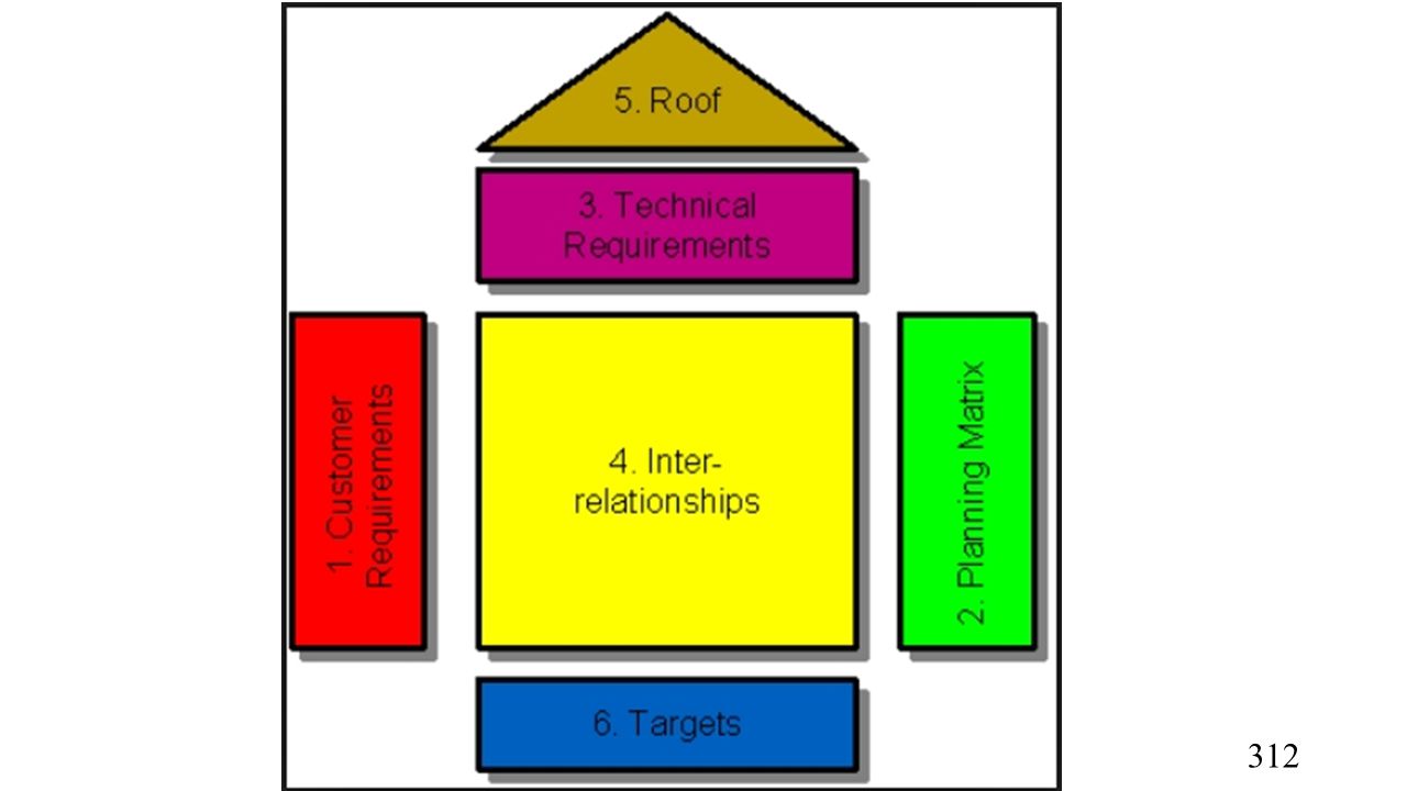
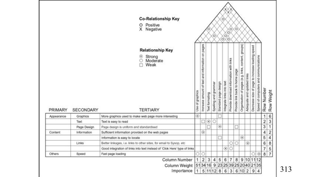
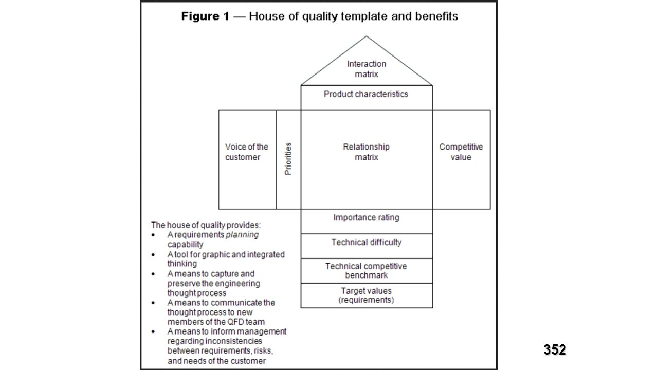


 Geometry (29%)>")


>")


