Download presentation
Presentation is loading. Please wait.

1
Science Olympiad Optics Color and Shadows

2
The Electromagnetic Spectrum.

3
Behavior of Light: Shadows - One Light Bulb
Use rays to predict what one would observe if there was one light source. Draw the “kissing” rays. The rays that just clear the barrier. Light Shadow Barrier Light So, what do we see on the screen?

4
Behavior of Light: Shadows - One Light Bulb
Use rays to predict what one would observe if there was one light source. There are many rays that leave the light bulb that go in all directions. Light Shadow Barrier Light

5
Behavior of Light - Two Light Bulbs
Use rays to predict what one would observe if there were two light sources. Light Draw the “kissing” rays from bulb, B1. Shadow Partial Bulb1 Draw the “kissing” rays from bulb, B2. Full (Dark) Shadow Shadow Partial Bulb2 Shadow from bulb, B1 and light from Bulb, B2. So, what do we see on the screen? Light
 Shadow. Shadow. Partial. Bulb2. Shadow from bulb, B1 and light from Bulb, B2. So, what do we see on the screen Light.")
6
So, what do we see on the screen? Light Green Red and
Behavior of Light - Two Light Bulbs Use rays to predict what one would observe if there were two light sources of different colors. Light Green Red and Shadow Partial Green Full (Dark) Shadow Shadow Partial Red So, what do we see on the screen? Light Green Red and
 Shadow. Shadow. Partial. Red. So, what do we see on the screen Light. Green. Red. and.")
7
Let’s review where the light shines.
Behavior of Light - Two Light Bulbs Use rays to predict what one would observe if there were two light sources of different colors. Full (Dark) Shadow Partial Red Light Green and Let’s review where the light shines.
 Shadow. Partial. Red. Light. Green. and. Let’s review where the light shines.")
8
Color By Addition. ~ Light!

9
RED + BLUE + GREEN = WHITE
Color by addition. Blue, red and green light from three different projectors. RED + GREEN = YELLOW RED + BLUE = MAGENTA BLUE + GREEN = CYAN RED + BLUE + GREEN = WHITE

10
Now you try this one and then I will show you the results.
RED GREEN Now you try this one and then I will show you the results.

11
RED SHADOW

12
Yellow RED Green

13
White Yellow Magenta Cyan RED + BLUE = MAGENTA RED + GREEN = YELLOW BLUE + GREEN = CYAN RED + BLUE + GREEN = WHITE

16
Science Olympiad Ray Optics Reflection

17
Lab - Reflection - Law of Reflection Part 1
Where does the reflection of something appear? Select what you think is correct. In front of the mirror. b) On the mirror. c) Behind the mirror. In the mirror. When you look in a mirror where does the reflection appear?
 On the mirror. c) Behind the mirror. In the mirror. When you look in a mirror where does the reflection appear")
18
A ray of light leaves the object and strikes the mirror, incident ray.
Where they intersect is called the image. More will be explained later. Image The ray reflects off the mirror, reflected ray. As it turns out, the distance from the object to the mirror, Do, is the same as the distance from the mirror to the object, Di. Di The image appears where the reflected rays intersect. They are diverging, they only intersect behind the mirror. DO Object

19
<i <r <r <i
Draw a normal (line perpendicular to the mirror) where the incident ray strikes the mirror. The angle between the incident ray and the normal is the angle of incidence, <i. Image The angle between the reflected ray and the normal is the angle of reflection, <r. <i <r <r <i Object
 where the incident ray strikes the mirror. The angle between the incident ray and the normal is the angle of incidence, <i. Image. The angle between the reflected ray and the normal is the angle of reflection, <r. <i. <r. <r. <i. Object.")
20
Law of Reflection The angle of incidence equals the angle of reflection. <i = <r The incident ray, the reflected ray and the normal line to the point of reflection all lie in the same plane. In other words, the angle of incidence and the angle of reflection lie in the same plane.

21
1. Locating objects in a plane mirror. A geometric analysis.
Image Incident Ray Angle of Incidence Normal A reflected ray comes from the direction of the image to the observer’s eye. Angle of Reflection Reflected Ray The actual reflected ray comes from the mirror to the observer’s eye. Observer The incident ray goes from the object to the point on the mirror where the reflected ray touches the mirror. The Angle of Incidence is the angle between the Incident Ray and the normal. The Angle of Reflection is the angle between the Reflected Ray and the normal. The normal is drawn perpendicular to the mirror where the incident ray and reflected ray meet.

22
2. Seeing objects in a mirror. A geometric analysis.
What makes the image appear behind the mirror? There are no rays of light back there. Object Image Observer #1 Observer #2 Eye If we have one eye at observer 1 and the other eye at observer 2, the nerves in the retina of our eyes send messages about the reflected rays that it sees to our brain for processing. Eye Our brain projects the reflected rays until they intersect which forms the image that appears behind the mirror..

23
2. Seeing objects in a mirror. A geometric analysis.
Image Observer #1 Observer #2 A C <i <r B <i = <r Law of Reflection. <A = <B Compliments of equal angles are equal. <B = <C Vertical angles are equal. <A = <C Both are equal to <B.

24
2. Seeing objects in a mirror. A geometric analysis.
<G = <H Supplements of equal angles are equal. Object Image Observer #1 Observer #2 D F <i <r E H G Similarly for Observer #1. <i = <r Law of Reflection. <D = <E Compliments of equal angles are equal. <E = <F Vertical angles are equal. <D = <F Both are equal to <E.

25
2. Seeing objects in a mirror. A geometric analysis.
Image Observer #1 Observer #2 H G A C These two triangles are congruent. Angle; <A = <C Side; common side. Angle; <G = <H

26
2. Seeing objects in a mirror. A geometric analysis.
Draw a straight line from object to image. Object Image Observer #1 Observer #2 D F These two triangles are congruent. Side; Corresponding sides of congruent triangles are equal. Angle; <D = <F Side; common side.

27
2. Seeing objects in a mirror. A geometric analysis.
DO Di Object Image Observer #1 Observer #2 I J Angle; <I = <J Not only are they corresponding angles of congruent triangles, they are supplementary angles. Thus they must be equal and 90°. DO = Di Corresponding sides of congruent triangles are equal. We have shown geometrically that the object is the same distance in front of the mirror as the image is behind the mirror. Both object and image lie on a line perpendicular to the mirror surface.

28
To Summarize The object is the same distance in front of the mirror as the image is behind the mirror. Both object and image lie on a line perpendicular to the mirror surface. Law of Reflection: The angle of incidence equals the angle of reflection. <i = <r The incident ray, the reflected ray and the normal line to the point of reflection all lie in the same plane.

29
1. Light from a flashlight shines on a mirror and illuminates one of the cards. Draw the reflected beam to indicate the illuminated card. 2. A periscope has a pair of mirrors in it. Draw the light path from object “O” to the eye of the observer. Let’s look at the extremes. Draw each normal to the mirror. Draw reflected rays. Remember <i = <r In order to see the bird, where is the starting point of the light?

30
Remember the Law of Reflection. <i = <r

31
Our mind locates where the reflected rays intersect, that is our mind projects the diverging reflected rays behind the mirror until they intersect and form the image.

32
Remember the Law of Reflection. <i = <r
Be careful, this time the mirror is not a plane (flat) mirror.
 mirror.")
33
The right view is correct
The right view is correct. The reflected view shows the underside of the bridge, or what you would see if your eye were as far below the water surface as your eye is above it.

34
Incident Ray. Reflected Ray. Abe can see himself. Trace the path of the light. Abe can see Bev. Bev can see Abe. The path of the ray of light is reversible. The mouse cannot see any of the reflections and neither Abe nor Bev can see the reflection of the mouse.

35
This is all the mirror that is needed.
No! Rays of light have to come to our eye from the direction of the image. The actual path of light so that we can see our feet. The actual path of light so that we can see the top of our head.

36
1. Which of the points shown can be seen reflected in the mirror by an observer at point O?
For construction purposes the mirror line may be extended. DO Di A’ Draw a line from the object perpendicular to the mirror to a distance behind the mirror. Measure DO and then measure the same distance behind the mirror to locate the image.

37
1. Which of the points shown can be seen reflected in the mirror by an observer at point O?
Repeat the procedure for all the points. A’ DO Di B’ DO Di C’ E’ D’ G’ F’

38
1. Which of the points shown can be seen reflected in the mirror by an observer at point O?
Draw a line from the observer, O, to the each image in order to see if if the necessary reflected ray hits the mirror. A’ No! B’ Yes! C’ Yes! E’ Yes! D’ Yes! G’ F’ Yes! Yes! Just barely.

39
1. Which of the points shown can be seen reflected in the mirror by an observer at point O?
DO Di Is there an easier way to do this problem using what we know about reflection? O’ From O’ draw the kissing rays to the mirror. These show the extremes that the observer can see in the mirror. Cannot see A, but can see B, C, D, E, F and maybe G. The path of a ray of light is reversible. Which means if I can see you, then you can see me. So, find the image of the observer, O.

40
2. Which of the points shown can be seen reflected in the mirror by an observer at point O?

41
2. Which of the points shown can be seen reflected in the mirror by an observer at point O?
Cannot see A O’ Can see B, C, D, E, F, O. Cannot see G

42
3. Locate and draw the image of triangle XYZ
3. Locate and draw the image of triangle XYZ. Then indicate the smallest mirror that will allow all of the reflection of the object to be seen by an observer at point O. X’ Z’ Y’

43
How much mirror is needed?
3. Locate and draw the image of triangle XYZ. Then indicate the smallest mirror that will allow all of the reflection of the object to be seen by an observer at point O. How much mirror is needed? THIS MUCH MIRROR. X’ Z’ Y’

44
How much mirror is needed?
4. Locate and draw the image of triangle XYZ. Then indicate the smallest mirror that will allow all of the reflection of the object to be seen by an observer at point O. How much mirror is needed? THIS MUCH MIRROR. X’ Y’ Z’

45
How much mirror is needed?
5. The drawing below shows woman AB with eyes at A and feet at B standing in front of a mirror. Show whether the woman can see all of her reflection in the mirror. A’ Can’t see feet. B’ How much mirror is needed?

46
How much mirror is needed?
6. If the woman steps back farther from the mirror will she see more of herself? Do a similar analysis as you did in problem #5 A’ B’ Still, can’t see feet. How much mirror is needed?

47
7. The drawings below show man AB with eyes at A and feet at B standing in front of a mirror. Show whether the man can see all of his reflection in mirror. A’ Can’t see. Can see. B’

48
7. The drawings below show man AB with eyes at A and feet at B standing in front of a mirror. Show whether the man can see all of his reflection in mirror. A’ Can see all. B’

49
10. There are two mirrors KL and MN facing each other
10. There are two mirrors KL and MN facing each other. Can the observer see the object at point A by looking in a mirror? If yes, trace the path of light from object “A” to the observer. In order to see A it must be a double reflection. Locate the image of A behind mirror KL. Locate the image of A’KL behind mirror MN. A’KL A”KL.MN

50
Yes, the double reflection of A can be seen by an observer at O.
10. There are two mirrors KL and MN facing each other. Can the observer see the object at point A by looking in a mirror? If yes, trace the path of light from object “A” to the observer. Trace reflected ray from A”KL,MN to observer. Trace incident ray to mirror MN from A’KL its object. Trace incident ray to mirror KL from A its object. Yes, the double reflection of A can be seen by an observer at O. A’KL A”KL.MN

51
11. There are two mirrors KL and MN facing each other
11. There are two mirrors KL and MN facing each other. Can the observer see the double reflection of object at point A? If yes, trace the path of light from object “A” to the observer. In order to see A it must be a double reflection. Locate the image of A behind mirror KL. Locate the image of A’KL behind mirror MN. A’KL A”KL.MN

52
There is no mirror here so A”KL,MN cannot be seen.
11. There are two mirrors KL and MN facing each other. Can the observer see the double reflection of object at point A? If yes, trace the path of light from object “A” to the observer. Trace reflected ray from A”KL,MN to observer. Trace incident ray to mirror KL from A its object. Trace incident ray to mirror MN from A’KL its object. There is no mirror here so A”KL,MN cannot be seen. A’KL A”KL.MN

53
Curved Mirrors

54
1. For the convex mirror shown below, show how each of the rays is reflected off the convex mirror.
The reflected rays appear to all come from a point. Since they don’t actually come from this point we refer to it as a virtual focal point. f What happens if we extend the reflected rays behind the mirror?

55
Principle Axis f Virtual Focal Point Principle Axis: A line that is drawn to the center of the mirror and that is perpendicular to a tangent to the arc of the mirror at its center.

56
Remember that the path of a ray of light is reversible.
A ray of light that approaches the mirror parallel to the principle axis reflects off the mirror as if it came from the virtual focal point. Remember that the path of a ray of light is reversible. A ray of light that approaches the mirror in the direction of the virtual focal point reflects off the mirror parallel to the principle axis.

57
Where does the image occur?
f Where does the image occur? Extend the reflected rays behind the mirror until they intersect. The image appears where the reflected rays intersect.

58
2. Draw the images in the following convex mirrors.

59
3. For the concave mirror shown below, show how each of the rays is reflected off the concave mirror. f All the reflected rays converge at a point called the focal point or the primary focus.

60
4. Parts of the mirror. Principle Axis C center of curvature f focal point The line that intersects the mirror at the very center and is perpendicular to a tangent to the arc of the mirror at that point is called the principle axis. The point on the principle axis where all the rays that approach the mirror parallel to the principle axis reflect and then cross is called the focal point. The center of the circle that is drawn to make the shape of the mirror is called the center of curvature. The focal point is half way from the center of curvature to the mirror.

61
5. As rays of light approach the mirror three of the rays are easy to use to trace their path off of the mirror. f C Image A ray of light that approaches the mirror parallel to the principle axis reflects off the mirror and passes through the focal point. A ray of light that passes through the focal point as it approaches the mirror reflects off the mirror parallel to the principle axis. A ray of light that passes through the center of curvature as it approaches the mirror reflects off the mirror along the same path.

62
5. As rays of light approach the mirror three of the rays are easy to use to trace their path off of the mirror. f C Image All rays of light that leave the object and strike the mirror reflect so that they pass through the image. The three that we illustrated are the easy ones to trace.

63
6. Let’s practice a few. object Image object Image object Image C f C

64
7. Instead of just a point, what if the object has some height, like an arrow.
Image b) f C
 f. C.")
65
7. Instead of just a point, what if the object has some height, like an arrow.

66
8. There are two types of images that are formed as illustrated above in #7.
a) The image in a, b, and c is called a real image. List some of the characteristics of a real image. b) The image in d is called a virtual image. List some of the characteristics of a virtual image. 1. The image is in front of the mirror. 1. The image is behind the mirror. 2. The image is inverted (upside down). 2. The image is erect. 3. Real light rays cross to form the image. 3. Projected (by the brain) light rays cross to form the image. 4. The image can be shown on a screen. 4. The image cannot be shown on a screen.
 The image in a, b, and c is called a real image. List some of the characteristics of a real image. b) The image in d is called a virtual image. List some of the characteristics of a virtual image. 1. The image is in front of the mirror. 1. The image is behind the mirror. 2. The image is inverted (upside down). 2. The image is erect. 3. Real light rays cross to form the image. 3. Projected (by the brain) light rays cross to form the image. 4. The image can be shown on a screen. 4. The image cannot be shown on a screen.")
67
Complete the following table to help illustrate how the image changes as the object is placed at different distances from the screen. Between f & C Smaller Real At C Same Size Real Beyond C Larger Real Behind the Mirror Larger Virtual At the Mirror Same Size Virtual At ∞ X X X X X X X X At f X X X X X X X X

68
Let’s see if we can derive some equations for spherical mirrors.
<A = <B. When two parallel lines are cut by a transversal the alternate interior angles are equal. f C A C E F D B <C = <D. When two parallel lines are cut by a transversal the alternate interior angles are equal. <E = <F. Vertical angles are equal. Triangle ACE is similar to triangle BDF. AAA = AAA

69
Let’s see if we can derive some equations for spherical mirrors.
Height of the object, Ho. Do Distance from object to mirror, Do. f C Ho Hi Height of the image, Hi. Di Distance from image to mirror, Di. Corresponding sides of similar triangles are proportional. Hi Ho = Di Do

70
Let’s see if we can derive some equations for spherical mirrors.
Ho Hi Di - f Similarly we can show that these two triangles are similar. Corresponding sides of similar triangles are proportional. Hi Ho = Di - f f

71
Let’s see if we can derive some equations for spherical mirrors.
Do - f f f C Ho Hi Di - f Lastly, we can show that these two triangles are similar. Corresponding sides of similar triangles are proportional. Hi Ho = f _ Do -f

72
Hi Ho = f _ Do -f Hi Ho = Di - f f f _ Do -f = f Di - f
Let’s see if we can derive some equations for spherical mirrors. Do - f f f C Ho Hi Di - f So, look. Hi Ho = f _ Do -f Hi Ho = Di - f f f _ Do -f = f Di - f and then Cross multiply f2 = DoDi – Dof – Dif + f2 DoDi = Dof +Dif

73
Let’s see if we can derive some equations for spherical mirrors.
DoDi = Dof + Dif Divide through by f. DoDi/f = Do + Di Divide through by D0Di. 1/f = 1/Do + 1/Di If breaking a plane mirror causes seven years of bad luck, what happens if you break a curved mirror? If, I do, I die!

74
To summarize: Hi/Ho = Di/Do which is also the magnification, M Hi/Ho = f/(Do – f) = (Di – f)/f 1/f = 1/Do + 1/Di If Di is negative, then the image is behind the mirror. If Di is negative, then Hi will also be negative and the image is virtual.

75
Both convex mirrors and concave mirrors can produce virtual images.
What is the difference between virtual images produced by a convex mirror and virtual images produced by a concave mirror? Convex mirrors have a virtual focal point, so the focal length of a convex mirror is negative. Convex mirrors produce only virtual images that can be the same size as the object or smaller. Concave mirrors produce virtual images when the object is between the focal point and the mirror. The virtual images are the same size as the object or larger.

76
Science Olympiad Ray Optics Refraction

77
As a ray of light passes from air into glass it bends (refracts).
As a ray of light passes from glass into air it bends (refracts) again. The refraction takes place at the boundary between the air and the glass (interface).
 again. The refraction takes place at the boundary between the air and the glass (interface).")
78
As it turns out light slows down as it enters the glass from the air.
The light speeds up as it leaves the glass and enters the air. By definition the index of refraction for glass: nglass = speed of light in air/speed of light in glass

79
Actually the index of refraction for glass:
nglass = speed of light in a vacuum/speed of light in glass The index of refraction for air, nair = Yes, light refracts when it comes from space and enters our atmosphere. In this case it is significant, but for our use in normal life the difference is not significant. nSubs = speed of light in a vacuum/speed of light in the substance. nSubs ≅ speed of light in a air/speed of light in the substance. To three significant figures, they are essentially the same.

80
The ratio sin<i/sin<r is a constant.
Angle of incidence Normal Incident Ray <i Glass Angle of refraction <r Refracted Ray A scientist name Snell noticed after many trials found that there is a relationship between the angle of incidence and the angle of refraction. The ratio sin<i/sin<r is a constant.

81
The ratio sinθair/sinθglass is a constant.
Angle in air Normal Incident Ray θair Glass Angle in glass θglass Refracted Ray It is also true that in refraction that the path of a ray of light is reversible. The ratio sinθair/sinθglass is a constant. nglass = vvac/vglass = sinθvac/sinθglass ≅ vair/vglass = sinθair/sinθglass

82
nSub = vvac/vSub = sinθvac/sinθSub ≅ vair/vSub = sinθair/sinθSub
Angle in air Normal Incident Ray θair Substance Angle in substance θglass Refracted Ray nSub = vvac/vSub = sinθvac/sinθSub ≅ vair/vSub = sinθair/sinθSub So what happens if one of the substances is something other than air? All these indices involve air and some substance. Let’s say light is going from glass to water.

83
nglass = sinθair/sinθglass
First Interface nglass = sinθair/sinθglass Air θair Second Interface θair nwater = sinθair/sinθwater Water θwater To start, let’s put air between the glass and water.

84
First Interface nglass = sinθair/sinθglass nglasssinθglass = sinθair Second Interface nwater = sinθair/sinθwater nwatersinθwater = sinθair If the interfaces are parallel then the two angles, θair are the same. Substituting: nglasssinθglass = nwatersinθwater

85
nglasssinθglass = nwatersinθwater
If we push the air out. Glass θglass Water θwater nglasssinθglass = nwatersinθwater To generalize: nXsinθX = nysinθy= nzsinθz = … as long as the interfaces are parallel.

86
Some indices of refraction:
nair = nwater = 1.33 nglycerine = 1.47 nLucite = 1.49 ncrown glass = 1.52 ndiamond = 2.42 In general the more dense the substance the greater the index of refraction. As light goes from a less dense substance (lower index of refraction) to a denser substance (higher index of refraction) the light ray bends towards the normal. <i is greater than <r. As light goes from a denser substance to a less dense substance the light ray bends away from the normal. <i is less than <r.
 to a denser substance (higher index of refraction) the light ray bends towards the normal. <i is greater than <r. As light goes from a denser substance to a less dense substance the light ray bends away from the normal. <i is less than <r.")
87
Some indices of refraction:
nair = nwater = 1.33 nglycerin = 1.47 nLucite = 1.49 ncrown glass = 1.52 ndiamond = 2.42 As light goes from a less dense substance (lower index of refraction) to a denser substance (higher index of refraction) the light ray bends towards the normal. <i is greater than <r. No matter how big the angle of incidence in the less dense substance the angle of refraction in the denser substance will be smaller. The largest angle of incidence in the less dense substance is 90°, so the angle of refraction in the denser substance will always be less than 90°.
 to a denser substance (higher index of refraction) the light ray bends towards the normal. <i is greater than <r. No matter how big the angle of incidence in the less dense substance the angle of refraction in the denser substance will be smaller. The largest angle of incidence in the less dense substance is 90°, so the angle of refraction in the denser substance will always be less than 90°.")
88
Air θair Glass θglass No matter how big the angle of incidence in the air the angle of refraction in the glass will be smaller.

89
Some indices of refraction:
nair = nwater = 1.33 nglycerine = 1.47 nLucite = 1.49 ncrown glass = 1.52 ndiamond = 2.42 As light goes from a denser substance to a less dense substance the light ray bends away from the normal. <i is less than <r. No matter how big the angle of incidence in the denser substance the angle of refraction in the less dense substance will be bigger. This leads to a problem because the largest possible angle of refraction in the less dense substance is 90°. So what happens as the angle of incidence gets bigger and bigger?

90
Eventually the angle of refraction in the air will be 90°.
Glass θcritical θglass No matter how big the angle of incidence in the glass the angle of refraction in the air will be bigger. Eventually the angle of refraction in the air will be 90°. We call the angle of incidence in this case the critical angle.

91
nglasssinθglass = nairsinθair nglasssinθcritical = 1.00Sin90°
In this case: nglasssinθglass = nairsinθair nglasssinθcritical = 1.00Sin90° nglasssinθcritical = 1 sinθcritical = 1/nglass Glass Air θcritical θair = 90° θcritical = sin-1(1/nglass) = sin-1(1/1.52) = 41.1° So what happens when the angle of incidence in the glass is greater than 41.1°?
 = sin-1(1/1.52) = 41.1° So what happens when the angle of incidence in the glass is greater than 41.1°")
92
Air θair Glass θglass θglass Actually when the incident ray strikes the interface some is refracted obeying the Law of Refraction. Some is also reflected internally in the glass obeying the law of reflection.

93
All of the ray is reflected internally obeying the law of reflection.
For this situation (glass to air) a ray with an angle of incidence greater than 41.1° will be totally reflected internally. Air θair Glass θ50° θ50° θglass θglass When the angle of incidence is greater than the critical angle, then there is no refraction. No ray enters the air! All of the ray is reflected internally obeying the law of reflection. This is called “Total Internal Reflection.”
 a ray with an angle of incidence greater than 41.1° will be totally reflected internally. Air. θair. Glass. θ50° θ50° θglass. θglass. When the angle of incidence is greater than the critical angle, then there is no refraction. No ray enters the air! All of the ray is reflected internally obeying the law of reflection. This is called Total Internal Reflection.")
94
nx > ny nglass = 1.52 > nwater = 1.33 In general terms:
nxsinθcritical = nysinθy = nysin90° = ny θcritical = sin-1(ny/nx) This only happens when light passes from a denser substance to a less dense substance. In other words when light goes from a substance with a big index of refraction to a substance with a smaller index of refraction. It would happen when light goes from glass to water, but not when light goes from water to glass. nglass = 1.52 > nwater = 1.33 nx > ny
 This only happens when light passes from a denser substance to a less dense substance. In other words when light goes from a substance with a big index of refraction to a substance with a smaller index of refraction. It would happen when light goes from glass to water, but not when light goes from water to glass. nglass = 1.52 > nwater = nx > ny.")
95
Where does she see the fish?
How does light go from the fish to her eye?

96
What happens if we have parallel interfaces?
Air Glass θglass θglass θa nasinθa = nglsinθgl = nasinθa The angle of incidence in air at the first interface equals the angle of refraction in air at the second interface.

98
What happens with sunlight and water droplets in the sky?
The light is refracted as it enters the water droplet, then there is total internal reflection, and then the ray is refracted again as it leaves the water droplet. The index of refraction for blue light is slightly greater than the index of refraction of the red light, so the blue ray is refracted more.

99
What happens with sunlight and water droplets in the sky?
If it is raining, but the sun starts to shine. If you place your back to the sun you may see a rainbow. The lower the sun is in the sky, the better the chance that you will see a rainbow.

100
Lenses

101
Since the light rays converge, we call this a converging lens.
Note that the ray bends towards the fatter part of the triangular prism. Since the light rays converge, we call this a converging lens. f If the lens is relatively thin, we can approximate the path by drawing a ray that is parallel to the principal axis to the center of the lens and then drawing it so it passes through the focal point.

102
The path of a ray of light is reversible
The path of a ray of light is reversible. We illustrated that rays traveling parallel to the principal axis from left to right converge at a point called the focal point on the right side of the lens. Principal Axis focal length focal length f f Then rays traveling parallel to the principal axis from right to left converge at a point called the focal point on the left side of the lens. A lens will have two focal points, both on the principal axis and one on each side of the lens. Each the same distance from the lens.

103
1. Locate the image of the object shown.
A ray that is parallel to the principal axis refracts through the lens and passes through the focal point on the other side of the lens. A ray that passes through the focal point refracts through the lens and continues parallel to the principal axis. A ray that passes through the center of the lens continues along in a straight line. Remember that these are the easy rays. All rays that leave the object and strike the lens intersect to form the image.

104
2. Where is the image when the object is far from the lens?
You can use any two of the following rays to locate the image. Ray parallel to principal axis Ray that goes in through the focal point Ray that passes through the center of the lens Sometimes it is easy to use all three, but you only need two of them.

105
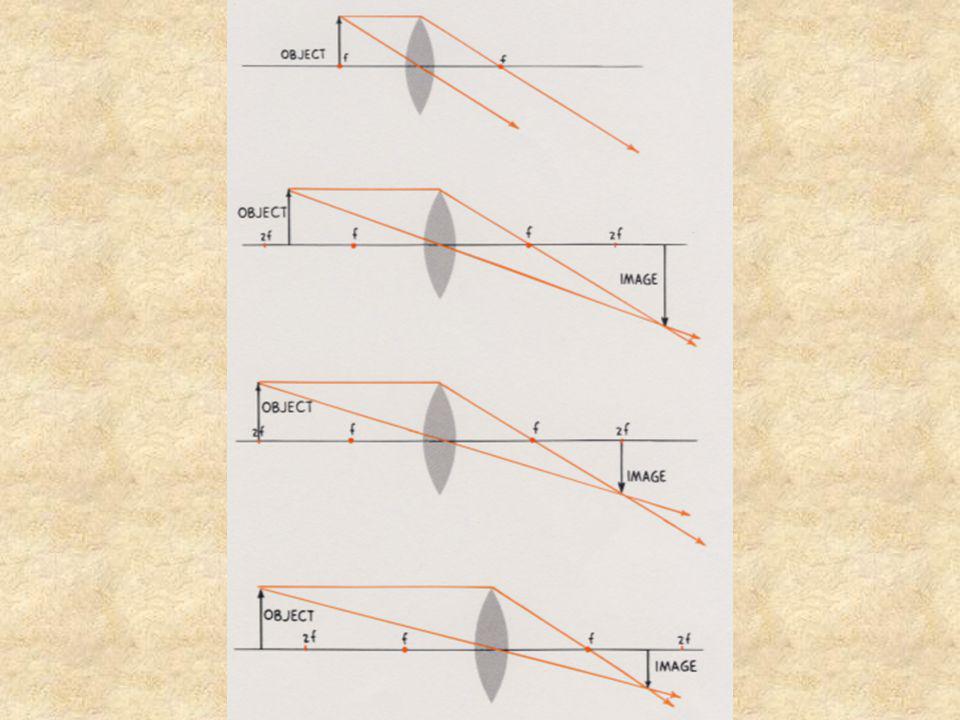
3. Where is the image when the object is twice the focal length (2f) from the lens?
4. Where is the image when the object is between 2f and f from the lens?

106
5. What happens when the object is between the focal point and the lens?

107
6. What happens when an object is placed the same distance from two different lenses?

109
Image size relative to object size
7. Now let us summarize what we have learned so far about the images formed by converging lenses. Object Location Image Location Image size relative to object size Type of image beyond “2f” from the lens between “2f” and “f” Smaller Real at “2f” Same size beyond “2f” Larger between “f” and the lens Same side as object Virtual at the lens at infinity at “f” XXXX

110
8. A ray of light that approaches the lens parallel to the principal axis refracts, diverging as if it came from the first focal point (the one on the same side of the lens). 9. A ray of light that is pointing towards the second focal point (the one on the other side of the lens) strikes the lens and refracts parallel to the principal axis.
 strikes the lens and refracts parallel to the principal axis.")
111
10. A ray of light that passes though the center of the lens is along a normal and thus passes straight through the lens (does not bend at all). Find the images in the following cases where an object is placed in front of a diverging lens. a)
")
112
Find the images in the following cases where an object is placed in front of a diverging lens.
12. What type of image is formed by a diverging lens? Virtual image that is smaller than the object.

113
This image is only created by the mind
This image is only created by the mind. The refracted light rays do not intersect, so our mind projects them back until the rays intersect forming a virtual image.

114
13. Let us compare virtual images formed by a diverging lens with virtual images formed by a converging lens. Find the image in each case. 14. How are these two images the same? Both images are virtual. 15. How are these two images different? The one from the converging lens is larger than the object, where as the one from the diverging lens is smaller than the object.

115
Deriving Lens Equations

116
Hi/Ho = Di/Do We can show that these two triangles are similar Ho f Hi
Ho = Height of the object Hi = Height of the image Do = Distance of the object to the lens (center) Hi/Ho = Di/Do Di = Distance of the image to the lens (center)
 Hi/Ho = Di/Do. Di = Distance of the image to the lens (center)")
117
Derive the equation 1/f = 1/Do + 1/Di
Di - f Ho f Do - f Hi Di Do Using the green similar triangles: Hi/Ho = f/(Do –f) Using the red similar triangles: Hi/Ho = (Di –f)/f Using our algebra we can show that: f/(Do –f) = (Di –f)/f and manipulating the equation we get: 1/f = 1/Do + 1/Di
 Using the red similar triangles: Hi/Ho = (Di –f)/f. Using our algebra we can show that: f/(Do –f) = (Di –f)/f. and manipulating the equation we get: 1/f = 1/Do + 1/Di.")
118
The Eye and Corrective Lenses

120
The eye Distant objects. Lens in eye has long focal length.
Image is in focus on the retina. Close objects. Lens in eye has short focal length. Image is in focus on the retina.

121
Hyperopia, farsightedness. Can see distant objects.
Image is in focus on the retina. For close objects the lens cannot shorten its focal length enough. Thus the image is in focus behind the retina. Use a converging lens to make the rays converge sooner and the image to form on the retina.

122
Myopia, nearsightedness. Can see close objects.
Image is in focus on the retina. For distant objects the lens cannot lengthen the focal length enough. Thus the image is in focus in front of the retina. Use a diverging lens to make the rays converge less and the image to form on the retina. Image is in focus on the retina.

123
Laser Shoot

124
Division B: Target on side of frame
Mirror Target Laser

125
Division C: Target behind barrier on back of frame
Mirror Mirror Laser

126
The End

Similar presentations


,>")


 increases, the angle of reflection (r)>")


 At this speed it can go around the world 8 times in one.>")


