Download presentation
Presentation is loading. Please wait.

1
Power Transfer Applications & Considerations
John Stark – Russelectric Inc.

2
Power Transfer Applications & Considerations
Selective Coordination and codes Power Transfer Applications & Considerations Design Considerations Transfer Switch Applications Bypass Functions (pros & cons) Timers Common Mistakes & Common Sense Tips
 Timers. Common Mistakes & Common Sense Tips.")
3
Transfer Equipment in a Common Scenario
Commercial Utility Power UPS UPS Batteries Network Computer Loads Transfer Switchgear Emergency Generators Generator Paralleling Control Switchgear Air conditioning, Lighting, Mechanical, Building Loads,etc. With regard to the emergency back-up and transfer scheme, it is incumbent upon engineers to select the proper equipment for the application. There are many considerations and they are becoming more with each decade.

4
Overview Recent changes to the National Electrical Code (NEC) require the selective coordination of overcurrent protective devices at hospitals and other mission-critical facilities. Transfer switches with 30-cycle closing and withstand ratings dramatically simplify designing to that requirement.
 require the selective coordination of overcurrent protective devices at hospitals and other mission-critical facilities. Transfer switches with 30-cycle closing and withstand ratings dramatically simplify designing to that requirement.")
5
What is Selective Coordination?
Definition (Article 100 – NEC) Localization of an overcurrent condition to restrict outages to the circuit or equipment affected, accomplished by the choice of overcurrent protective devices and their ratings. Article 100 provides the Code definition. Here is another way to describe it: “For the full range of possible overcurrents, the act of isolating an overloaded or faulted circuit from the remainder of the electrical system, thereby eliminating unnecessary power outages.” The circuit causing the overcurrent is isolated by the selective operation of only that overcurrent protective device which is closest upstream to the overcurrent condition.
 Localization of an overcurrent condition to restrict outages to the circuit or equipment affected, accomplished by the choice of overcurrent protective devices and their ratings. Article 100 provides the Code definition. Here is another way to describe it: For the full range of possible overcurrents, the act of isolating an overloaded or faulted circuit from the remainder of the electrical system, thereby eliminating unnecessary power outages. The circuit causing the overcurrent is isolated by the selective operation of only that overcurrent protective device which is closest upstream to the overcurrent condition.")
6
Selective Coordination Requirements
Selective coordination was first required by the NEC in 1993 for elevator circuits. Amendments to the Code in 2005 and 2008 strengthened the requirements and expanded them to include emergency and legally required standby systems, as well as critical operations power systems. Selective coordination, as defined in the 2008 NEC, is the “localization of an overcurrent condition to restrict outages to the circuit or equipment affected, accomplished by the choice of overcurrent protective devices and their ratings or settings.” It is a complicated process of coordinating the ratings and settings of overcurrent protective devices, such as circuit breakers, fuses, and ground fault protection relays, to limit overcurrent interruption (and the resultant power outages) to the affected circuit or equipment (the smallest possible section of a circuit). In other words, the only overcurrent protective device that should open is the device immediately “upstream” from the circuit/equipment experiencing an overcurrent condition.
 to the affected circuit or equipment (the smallest possible section of a circuit). In other words, the only overcurrent protective device that should open is the device immediately upstream from the circuit/equipment experiencing an overcurrent condition.")
7
Proper Selective Coordination is becoming more and more of an engineering consideration and is being enforced more often… Refer to IAEI handout “Selective coordination restricts outages to the circuit or equipment affected, ensuring reliability of electrical power.”

8
NEC 2008 –Verbiage on Selective Coordination
NEC(2008) Coordination: requires “Emergency system(s) overcurrent devices shall be selectively coordinated with all supply side overcurrent protective devices.” NEC(2008) Coordination: requires “Legally required standby system(s) overcurrent devices shall be selectively coordinated with all supply side overcurrent protective devices.” NEC(2008) Application of other articles: requires “The essential electrical system shall meet the requirements of Article 700.” The overcurrent protective devices may include the following: Molded Case Circuit Breakers Fused devices Insulated Case Circuit Breakers Air Power Circuit breakers
 Coordination: requires Emergency system(s) overcurrent devices shall be selectively coordinated with all supply side overcurrent protective devices. NEC(2008) Coordination: requires Legally required standby system(s) overcurrent devices shall be selectively coordinated with all supply side overcurrent protective devices. NEC(2008) Application of other articles: requires The essential electrical system shall meet the requirements of Article 700. The overcurrent protective devices may include the following: Molded Case Circuit Breakers. Fused devices. Insulated Case Circuit Breakers. Air Power Circuit breakers.")
9
One-line G Utility 4000A APCB APCB's (Air Power Circuit Breaker) are typically 30 cycle withstand devices. 1600A APCB 1600A APCB ICCB's (Insulated Case Circuit Breaker) are 30 cycle withstand or up to 4 Cycle Instantaneous. ATS 800A ICCB MCCB's (Molded Case Circuit Breaker) typically instantaneous or Current Limiting Devices. 400A MCCB An overcurrent event (overload, short circuit, or ground fault) here should trip the 400A MCCB
 are 30 cycle withstand or up to 4 Cycle Instantaneous. ATS. 800A. ICCB. MCCB s (Molded Case Circuit Breaker) typically instantaneous or Current Limiting Devices. 400A. MCCB. An overcurrent event (overload, short circuit, or ground fault) here should trip the 400A MCCB.")
11
Selective Coordination
G Utility 4000A APCB 1600A 800A ICCB 400A MCCB In the absence of other means to satisfy selective coordination, the ATS must withstand a fault or even close on potential fault to be properly coordinated. ATS ATS Fault on load side of ATS could see up to 30 cycles of fault current -depending on the Air Power Circuit Breaker settings that is feeding it- and could travel through the ATS and the ATS contacts. If the 400A MCCB does not trip/clear…

12
More on Selective Coordination
Requirements Selective coordination requirements for life safety are not a new concept for the Code. There has been a Code requirement to coordinate selectively the over-current protective devices for elevator circuits since 1993. Most engineers agree this is the simplest way to assure coordination, however….. Breakers Instantaneous circuit breakers will not coordinate properly because typically, they aren’t adjustable. Fuses

13
Code Requirements Article 517 Health Care Facilities
Application of Other Articles Article 620 Elevators, etc Selective Coordination (2008) Article 700 Emergency Systems 700.9 (B)(5)(b), Exception Article 701 Legally Required Standby Systems Coordination Article 708 Critical Operations Power Systems Selective Coordination
 Article 700 Emergency Systems (B)(5)(b), Exception. Article 701 Legally Required Standby Systems Coordination. Article 708 Critical Operations Power Systems Selective Coordination.")
14
2005 Code Adoption 2005 NEC 1999 NEC 2002 NEC Local Adoption

15
2008 Code Adoption AK State Adopted Unincorporated Areas
WA ME MT ND M I VT MN NH NY OR WI MA ID CT RI SD M I WY PA NB NJ IA Expected July 2010 OH MD DE NV IN IL WV Expected July 10’ UT VA CA CO KS MO KY Expected January 2011 NC TN State Adopted AR SC AZ NM OK GA S. Carolina Code Council adopted 2009 IRC with 2008 NEC 3/22/10 with implementation TX MS AL State Adopted Unincorporated Areas LA AK FL 2008 NEC – 32 States Basically 2002 NEC but some islands back to 1993 NEC 2005 NEC – 8 States Local Adoption – (10) Note: Some local adoption states have earlier than 2005 adoptions in some jurisdictions Revised April 19, 2010
 Note: Some local adoption states have earlier than 2005 adoptions in some jurisdictions. Revised April 19,")
16
Code Rulings Panel 13 Statement: Panel 20 Statement:
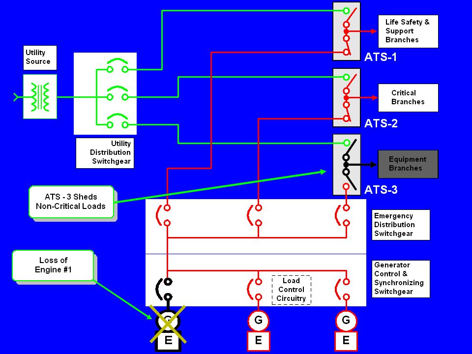
In the 2008 Code Cycle there were challenges to the selective coordination requirement. Proposal proposed the elimination of the selective coordination requirement for But Code Panel 13 rejected this proposal by a vote of 9-4. To follow is their statement: Panel 13 Statement: “This proposal removes the selective coordination requirement from the mandatory text and places it in a non-mandatory FPN (fine print note). The requirement for selective coordination for emergency system over-current devices should remain in the mandatory text. Selective coordination increases the reliability of the emergency system. The current working of the NEC is adequate. The instantaneous portion of the time-current curve is no less important than the long time portion. Selective coordination is achievable with the equipment available now”. Code Panel 20, which was responsible for the new Article 708, summed up the need for selective coordination in their statement to Comment (20-13), which was another proposal for the deletion of the selective coordination requirement. This comment was rejected The actual panel statement to Comment 20-13: Panel 20 Statement: “The overriding theme of Articles 585 (renumbered to 708) is to keep the power on for vital loads. Selective coordination is obviously essential for the continuity of service required in critical operations power systems. Selective coordination increases the reliability of the COPS system.”
. The requirement for selective coordination for emergency system over-current devices should remain in the mandatory text. Selective coordination increases the reliability of the emergency system. The current working of the NEC is adequate. The instantaneous portion of the time-current curve is no less important than the long time portion. Selective coordination is achievable with the equipment available now . Code Panel 20, which was responsible for the new Article 708, summed up the need for selective coordination in their statement to Comment (20-13), which was another proposal for the deletion of the selective coordination requirement. This comment was rejected The actual panel statement to Comment 20-13: Panel 20 Statement: The overriding theme of Articles 585 (renumbered to 708) is to keep the power on for vital loads. Selective coordination is obviously essential for the continuity of service required in critical operations power systems. Selective coordination increases the reliability of the COPS system.")
17
Exceptions to Code Rulings Refer to IEEE handout “Selective Coordination versus Arc Flash…” page 12
There are numerous proposals being adopted by States and/or City or local governmental bodies which modify the selective coordination requirements. The most commonly heard proposals fall into two categories: 1. Allow the degree of selective coordination needed to be the responsibility of the qualified person responsible for the project. (The Commonwealth of Massachusetts was the first State to adopt such a proposal as an exception to the Articles in , and , which require selective coordination as follows: Exception No. 2: Where the system design is under the control of a licensed professional engineer engaged in the design or maintenance of electrical installations, the selection of overcurrent protective devices shall be permitted to coordinate to the extent practicable. The design shall be documented, stamped by the professional engineer, and made available for review by the authority having jurisdiction.

18
Exceptions to Code Rulings (cont.)
2. Proposals to modify the NEC requirement for selective to only be required for above a specific time. The leading proposal is 0.1 seconds (6 cycles) and above. The State of Oregon recently adopted a proposal submitted by the National Electrical Contractors Assoc., Oregon Pacific Cascade Chapter, as Statewide Alternate Method No. OESC applying to Articles in , and This states the following: “The requirements in NEC , and for selective coordination may be demonstrated by providing a selective coordination study utilizing trip-curve data in the range of 0.1 seconds or more. Substantiation for this proposal included: 1). “…selective coordination is not always possible or practical for all fault current levels when protection is provided by MCCB’s. The requirement for “total” selective coordination means that over current protection devices must be coordinated for all faults, regardless of their magnitude or duration, including the most extreme case, the bolted fault. However, bolted three phase faults which rapidly generate extremely high current in the instantaneous range rarely occur in practice, except at start-up when interruption of power due to a lack of coordination is not likely to compromise safety...” “In order to achieve total short circuit selective coordination, the size of upstream overcurrent protective devices may need to be increased and/or time delay trip characteristics increased, thereby possibly increasing the arc flash hazard.” “Findings: By omitting the instantaneous range from the requirements for selective coordination, reasonable and affective safety can (still) be achieved. Signing supervisors and engineers can use readily available and published time current curves to determine if a system is selectively coordinated to a substantial degree without having to relay on unregulated manufacturer testing data and inconsistent engineering and design practices.”
 and above. The State of Oregon recently adopted a proposal submitted by the National Electrical Contractors Assoc., Oregon Pacific Cascade Chapter, as Statewide Alternate Method No. OESC applying to Articles in , and This states the following: The requirements in NEC , and for selective coordination may be demonstrated by providing a selective coordination study utilizing trip-curve data in the range of 0.1 seconds or more. Substantiation for this proposal included: 1). …selective coordination is not always possible or practical for all fault current levels when protection is provided by MCCB’s. The requirement for total selective coordination means that over current protection devices must be coordinated for all faults, regardless of their magnitude or duration, including the most extreme case, the bolted fault. However, bolted three phase faults which rapidly generate extremely high current in the instantaneous range rarely occur in practice, except at start-up when interruption of power due to a lack of coordination is not likely to compromise safety... In order to achieve total short circuit selective coordination, the size of upstream overcurrent protective devices may need to be increased and/or time delay trip characteristics increased, thereby possibly increasing the arc flash hazard. Findings: By omitting the instantaneous range from the requirements for selective coordination, reasonable and affective safety can (still) be achieved. Signing supervisors and engineers can use readily available and published time current curves to determine if a system is selectively coordinated to a substantial degree without having to relay on unregulated manufacturer testing data and inconsistent engineering and design practices.")
19
Arc Flash Considerations Refer to IEEE handout “Selective Coordination versus Arc Flash…” page 10
This is the other side of the argument regarding the subject of Selective Coordination VS Arc Flash Considerations. The presenter will not delve into this side of the argument, as he is in the business of providing emergency power to critical facilities and therefore is in the camp of having a non-sensitive, robust type system, selectively coordinated, that facility managers want to perform well when called upon. In cases of catastrophic outages, Arc flash considerations might take a back seat to keeping as much of the facility up and running as possible and only Tripping CB’s closest to the fault. For more details on the ARC Flash concerns, and that whole side of the argument, please refer to your handout.

20
UL 1008 Withstand Test 34.1 When tested under the conditions described in 34.2 – 34.15, a transfer switch shall withstand the designated levels of current until the over-current protective devices open or for a time as designated in At the conclusion of the test: The switch shall be capable of being operated by its intended means; The fuse mentioned in shall not open, There shall be no breakage of the switch base to the extent that the integrity of the mounting of live parts is impaired, The door shall be prevented by its latch, without bolt or lock installed therein, from being blown open, and deformation of the door alone is not determined to be unacceptable; No conductor shall have pulled out of a terminal connector and there is no damage to the conductor insulation or the conductor (see 41.56); and For a plug in or draw out unit, the point of contact is to be the same both mechanically and electrically as before the test.
; and. For a plug in or draw out unit, the point of contact is to be the same both mechanically and electrically as before the test.")
21
UL 1008 Closing Test 36.1 When tested in accordance with 36.2, a transfer switch shall comply with the requirements in 34.1(a) –(f). 36.1 Revised September 18, 1996 36.2 The sample for this test is to be that used for the withstand test. Test procedures and conditions for the closing test are to be as described in 34.3 – The switch is to be closed on the circuit. 36.3. The test (for close on) current shall be the same as that used in the withstand test.
 current shall be the same as that used in the withstand test.")
22
UL 1008 Short Circuit Test History
Around 1989 UL introduced an optional 3 cycle test for any over- current protection device. Prior to this, manufactures could test with any over-current device. If a manufacturer didn’t test to 3 cycles, they would be required provide a label that lists all breakers that the switch was “coordinated with”. This requirement did not take into consideration air power circuit breakers APCB’s. Some of these breakers were 4-5 cycle devices (GE AKR and Westinghouse DS) January 9th, 2002 UL introduced an optional short time current rating test. A withstand and a close and withstand test is required to get a UL short time rating.
 January 9th, 2002 UL introduced an optional short time current. rating test. A withstand and a close and withstand test is required to get a UL short time rating.")
23
UL 1008 Short Time Current Test
36A.1 A switch marked with a short-time current rating in accordance with shall be tested under the conditions described in 36A.2 -36A.12 and shall withstand the short-time current for the period specified. At the conclusion of the test: The transfer switch shall be capable of being operated by its intended means, The fuse mentioned in 36A.7 shall not open, There shall not be any damage to the switch base to the extent that the integrity of the mounting of live parts is impaired, The door shall be restricted by its latch, without bolt or lock installed therein, from being blown open. Deformation of the door itself is not reason for rejection, No conductor shall have pulled out of a terminal connector and there shall not be any damage to the conductor insulation or the conductor (see 41.56), For a plug-in or draw-out unit, the point of contact shall be the same both mechanically and electrically as before the test, The Temperature Test, Section 29, shall be performed on the transfer switch at the completion of the tests described in 36A.8 and 36A.9, without maintenance, and the temperature rise shall not exceed the values given in Table 29.1, increased by 10° C or 18° F, and The Dielectric Voltage-Withstand Test (Repeated), Section 36B, shall be performed on the transfer switch at the completion of the tests described in 36A.8 and 36A.9.
, For a plug-in or draw-out unit, the point of contact shall be the same both mechanically and electrically as before the test, The Temperature Test, Section 29, shall be performed on the transfer switch at the completion of the tests described in 36A.8 and 36A.9, without maintenance, and the temperature rise shall not exceed the values given in Table 29.1, increased by 10° C or 18° F, and. The Dielectric Voltage-Withstand Test (Repeated), Section 36B, shall be performed on the transfer switch at the completion of the tests described in 36A.8 and 36A.9.")
24
UL 1008 Overload Test Table 28.1 Overload Test
Transfer switch equipment shall perform in an acceptable manner, as intended by the manufacturer, when subjected to an overload test consisting of the number of operations specified in Table 28.1, controlling a test current as described in Table 28.2. Table 28.1 Overload Test Switch rating, amperes Number of cycles of operation Rate of Operation* 0-300 2501 and above 50 25 3 1 per minute 1 per 2 minutes 1 per 3 minutes 1 per 4 minutes 1 per 5 minutes Table 28.2 Method of determining test current for overload tests on transfer switches Device used for Device rated in amperes Power test current Factor Motor loads or total system a-c 6 times rated current 28.4 A cycle is defined as making and breaking the required test current on both the normal and alternate contacts. During the test, the alternate source shall be displaced 120 electrical degrees from the normal source for a 3 phase supply or 180 electrical degrees for a single phase supply. 28.6 The minimum on time in each contact position is to be 1/6 second (ten electrical cycles based on a 60Hz source), unless automatic tripping of the over-current device occurs.
, unless automatic tripping of the over-current device occurs.")
25
Method of determining test current for endurance tests
UL 1008 Endurance Test 30.1 A transfer switch shall perform as intended when subjected to an endurance test controlling a test current as described in Table 30.1 and at a rate and number of cycles described in Tables 30.2 and 30.3. Table 30.1 Method of determining test current for endurance tests The test cycle is to be 1 second “on” and 59 seconds “off”. A controller may be operated at a rate of more than 1 cycle per minute if synthetic loads are used or if a sufficient number of banks of lamps controlled by a each bank will cool for at least 59 seconds between successive applications of current. Table 30.2 Endurance test cycles for emergency system switches including legally required stand-by systems.

26
UL 1008 Temperature Test 29.1 Transfer switches when tested under the conditions described in 29.2 – shall not attain a temperature at any point high enough to constitute a risk of fire or to damage any materials employed in the device, and shall not show temperature rises at specific points greater than those indicated in Table 29.1 29.2 For the temperature test the transfer switch is to be operated under intended use conditions and is to carry its test current continuously at the test potential specified in Table 24.1. 29.3 The test current shall be 100 percent of the rated current.

27
Overcurrent Protective Devices
Molded Case Circuit Breakers –MCCB (UL489) May be Current Limiting to 200KA Long Time Overcurrent Instantaneous Interruption is less than 3 cycles Fuses and Fused Devices Current Limiting Mostly used on 200KA circuits Insulated Case Circuit Breakers -ICCB (UL489) Instantaneous Interruption is typically less than 4 cycles Short Time delay available (30 cycles) with Instantaneous over-ride Low Voltage Air Power Circuit Breakers -APCB (UL1066) Instantaneous Interruption is typically less than 4 cycles? Short Time delay available (30 cycles) without Instantaneous ?
 May be Current Limiting to 200KA. Long Time Overcurrent. Instantaneous Interruption is less than 3 cycles. Fuses and Fused Devices. Current Limiting. Mostly used on 200KA circuits. Insulated Case Circuit Breakers -ICCB (UL489) Instantaneous Interruption is typically less than 4 cycles. Short Time delay available (30 cycles) with Instantaneous over-ride. Low Voltage Air Power Circuit Breakers -APCB (UL1066) Instantaneous Interruption is typically less than 4 cycles Short Time delay available (30 cycles) without Instantaneous")
28
Low Voltage Air Power Circuit Breakers
APCB’s are ideal protective devices for the application of selective tripping. Short Circuit Duty Cycle: Oc,15 s – CO (applying fault current to a closed CB for ½ second [30 cycles] separated by 15 seconds of zero current flow, then close on fault current for another ½ second [30 cycles] ). This test may be performed with or without an instantaneous override on the closing cycle. The GE AKR was tested without the instantaneous. Note some breakers now have a “Trip Free” feature in which the breaker will still clear a fault without instantaneous trip. Opinions vary on whether this is desirable or not in emergency power systems. Short Time Current ANSI C (2)-1990 Short-Time Current Duty Cycle Application. The applicable short-time current duty cycle for unfused circuit breakers consists of two periods of 1/2s current flow, separated by a 15 s interval of zero current.
. This test may be performed with or without an instantaneous override on the closing cycle. The GE AKR was tested without the instantaneous. Note some breakers now have a Trip Free feature in which the breaker will still clear a fault without instantaneous trip. Opinions vary on whether this is desirable or not in emergency power systems. Short Time Current. ANSI C (2) Short-Time Current Duty Cycle Application. The applicable short-time current duty cycle for unfused circuit breakers consists of two periods of 1/2s current flow, separated by a 15 s interval of zero current.")
29
Selective Coordination - Good
No overlapping fault current of individual devices. This is coordinated properly. In a perfect world this is great.

30
Selective Coordination - BAD
ATS Feeder Breaker In this case, since it takes 8 cycles for the upstream breaker to clear the fault, a 3 cycle rated transfer switch is inadequate. 8 cycles to clear

31
Complete Coordination
A 30 cycle UL rated Transfer Switch truly gives you complete coordination with any over-current protective device.

32
ATS APPLICATIONS Open Transition Closed Transition Bypass/Isolation Load Break Bypass/Isolation No Load Break Medium Voltage ATS

33
Simple One-line, of ATS Transferring Between Utility & Generator
Engine shuts down system returned to normal operation Unloaded engine cool down period Utility is Restored Load is fed by emergency power Utility is Lost Simple One-line, of ATS Transferring Between Utility & Generator

34
Open Transition Transfer (one line)
Makes Overlapping Neutral Vs N E L Breaks N E L Before

35
Closed Transition Transfer (one-line)
Important consideration: CT ATS’s should have a fail to transfer failsafe feature. It’s best that this feature is designed to work independently, outside the control logic.

36
Important consideration: CT ATS’s should have a fail to transfer failsafe feature. It’s best that this feature is designed to work independently, outside the control logic.

37
In-Phase Monitor, Principal of Operation
In-Phase Monitor for Switching Inductive Loads or for Proper Closed Transition Switching (between two available sources) In-Phase Monitor, Principal of Operation A feature within the controller (or a synchro-check relay in old designs) where voltage values from source one and Source two are monitored through input signals to the controller. The controller compares the two voltage levels and phase relationship between the frequencies of both sources and will allow a transfer only when the voltage and frequency (of both sources) are within acceptable limits. Typical set points: 5% - 20% nominal volts Phase angle adjustment: 6 – 20 Electrical degrees Source 1 Source 2 ATS ATS
 In-Phase Monitor, Principal of Operation. A feature within the controller (or a synchro-check relay in old designs) where voltage values from source one and Source two are monitored through input signals to the controller. The controller compares the two voltage levels and phase relationship between the frequencies of both sources and will allow a transfer only when the voltage and frequency (of both sources) are within acceptable limits. Typical set points: 5% - 20% nominal volts Phase angle adjustment: 6 – 20 Electrical degrees. Source 1. Source 2. ATS. ATS.")
38
In-Phase Monitor for Switching Inductive Loads (between two available sources)
Pros: Cons: Introduces more sensitive and adjustable electronics and circuitry into the system. With some manufacturers this feature can be a significant cost savings over dual operator. If an acceptable window of voltage and frequency is not achieved, desired transfer will not happen. Example: ATS needs to return to utility after being in the engine generator (emergency) position… engine speed running erratically, no window achieved… switch in remote location… ATS remains on generator until it runs out of fuel. ATS
 position… engine speed running erratically, no window achieved… switch in remote location… ATS remains on generator until it runs out of fuel. ATS.")
39
L E E L E L 1 N N N 2 Operator #1 drives the normal source contacts
Dual Operator Switching for Inductive Loads (open transition, between two available sources) Operator #1 drives the normal source contacts open 1 L N E N E L N E L The load source is disconnected for an adjustable period to allow regenerative power to decay Operator #2 then drives the emergency source contacts closed 2
 Operator #1. drives the. normal source contacts. open. 1. L. N. E. N. E. L. N. E. L. The load source is disconnected for an adjustable period to allow regenerative power to decay. Operator #2. then drives the emergency. source contacts. closed. 2.")
40
Dual Operator for Switching Inductive Loads (open transition, between two available sources)
Pros: Very reliable. Positive transfer without reliance on sensitive monitors. The switch will always transfer without the load experiencing a “bump”. L N E With an inherent dual operator design, ATS has an ancillary benefit in that it can also be used as a dynamic load shed device, completely controllable, either automatically, manually or in a control scheme.

42
Dual Operator for Switching Inductive Loads (open transition, between two available sources)
Cons: Depending on the manufacturer this can be an expensive solution. L N E Slight delay on transfers

43
ATS Contact Assembly

44
ATS Contact Assembly

45
Operating Speed is Crucial for Proper Arc Suppression
Different approaches Unidirectional Motor with over center spring mechanism Springs & Linkage Motor Operator Quick Solenoid Operator

46
Bypass/Isolation Functions
A Bypass/Isolation unit is a switch within a switch… Bypass switching section ATS switching section (mounted in a draw-out assembly) Power can be maintained to load during ATS failure and until the ATS is repaired. Provides a means of bypassing the ATS for maintenance Unit can be operated as a manual transfer switch until the automatic portion is serviced and/or repaired
 Power can be maintained to load during ATS failure. and until the ATS is repaired. Provides a means of bypassing the ATS for maintenance. Unit can be operated as a manual transfer switch until. the automatic portion is serviced and/or repaired.")
47
Bypass/Isolation Functions
Variations on the Theme Bypass feature used mainly for maintenance of the automatic transfer switch portion of the unit (no load break bypass) Bypass feature used mainly in emergency situations (load break bypass) ATS Portion of unit may be open transition or closed transition, regardless of no load or load break bypass
 Bypass feature used mainly in emergency situations. (load break bypass) ATS Portion of unit may be open transition or closed. transition, regardless of no load or load break bypass.")
48
Bypass/Isolation Functions
Variations on the Theme No load break bypass Where maintenance of the ATS with no interruption in service is the priority

49
X No load break bypass Pros: Cons:
Cannot bypass the ATS portion of the unit to the alternate source without an interruption to the load Pros: Cons: Can bypass the ATS portion of the unit without disturbing the load (as long as the operator is bypassing the unit to the SAME source that the ATS is positioned/connected to). RTB(D) - Load Break design (Break-Before- Make Bypass) NORMAL LOAD EMERGENCY NORM ISOLATE ATS BPN BPE AUTO Cannot bypass to Emergency in the event of a combined Normal source failure and ATS fail to transfer without either manually transferring the ATS first, or bypassing the ATS to the source it is positioned/connected to, isolating it and then bypassing to the alternate source. This adds several or many steps. X Routine maintenance on ATS portion of units (not combined with UPS back-up) is made easy by no interruption to the load during the bypass function. Design relies on both electrical and mechanical interlocking, arguably reducing reliability. (This interlocking cannot be isolated, so unit must be taken completely off line for servicing.)
. RTB(D) - Load Break design (Break-Before- Make Bypass) NORMAL. LOAD. EMERGENCY. NORM. ISOLATE. ATS. BPN. BPE. AUTO. Cannot bypass to Emergency in the event of a combined Normal source failure and ATS fail to transfer without either manually transferring the ATS first, or bypassing the ATS to the source it is positioned/connected to, isolating it and then bypassing to the alternate source. This adds several or many steps. X. Routine maintenance on ATS portion of units (not combined with UPS back-up) is made easy by no interruption to the load during the bypass function. Design relies on both electrical and mechanical interlocking, arguably reducing reliability. (This interlocking cannot be isolated, so unit must be taken completely off line for servicing.)")
50
Bypass/Isolation Switch One-Line Diagram (Normal operating mode)
Bypass/Isolation Functions Variations on the Theme Load break bypass Where simplicity of operation is critical during an emergency condition Bypass/Isolation Switch One-Line Diagram (Normal operating mode)
")
51
Load Break Bypass Switches
Contacts Diagram showing a normal operating state.

52
Load Break Bypass Switches
Bypass operation Load Break Contacts Bypass Handle

53
Load Break Bypass Switches
Bypassing to normal Load Break Contacts Bypass Handle Load Momentarily Disconnected

54
Load Break Bypass Switches
NORMAL LOAD EMERGENCY NORM ISOLATE ATS BPN BPE AUTO Isolating the ATS Portion LOAD BYPASSED TO NORMAL

55
Load Break Bypass Switches
NORMAL LOAD EMERGENCY NORM ISOLATE ATS BPN BPE AUTO LOAD BYPASSED TO NORMAL NORMAL LOAD EMERGENCY NORM ISOLATE ATS BPN BPE AUTO Isolating the ATS Portion LOAD BYPASSED TO NORMAL

56
Load Break Bypass Switches
NORMAL LOAD EMERGENCY NORM ISOLATE ATS BPN BPE AUTO LOAD BYPASSED TO NORMAL NORMAL LOAD EMERGENCY NORM ISOLATE ATS BPN BPE AUTO If the transfer switch portion is bypassed & isolated to normal and the normal power fails an engine start signal will initiate... LOAD BYPASSED TO NORMAL

57
Load Break Bypass Switches
NORMAL LOAD EMERGENCY NORM ISOLATE ATS BPN BPE AUTO LOAD BYPASSED TO NORMAL NORMAL LOAD EMERGENCY NORM ISOLATE ATS BPN BPE AUTO If the transfer switch portion is bypassed & isolated to normal and the normal power fails an engine start signal will initiate... LOAD BYPASSED TO NORMAL

58
Load Break Bypass Switches
NORMAL LOAD EMERGENCY NORM ISOLATE ATS BPN BPE AUTO Emergency Power Available LOAD STILL BYPASSED TO NORMAL

59
Load Break Bypass Switches
NORMAL LOAD EMERGENCY NORM ISOLATE ATS BPN BPE AUTO Switch Bypassed to Emergency

60
Load Break Bypass Switches
Should Normal Source return switch can still be racked in…

61
Load Break Bypass Switches
ATS RTB(D) - Load Break design (Break-Before- Make Bypass) NORM ISOLATE AUTO BPN BPE BPN BPE Should Normal Source return switch can still be racked in… LOAD NORMAL EMERGENCY
 - Load Break design (Break-Before- Make Bypass) NORM. ISOLATE. AUTO. BPN. BPE. BPN. BPE. Should Normal. Source return. switch can. still be. racked in… LOAD. NORMAL. EMERGENCY.")
62
Load Break Bypass Switches
Pros: Cons: When performing routine testing or maintenance, special consideration must be given to the “blink”. Maintenance will probably need to be scheduled and coordinated so the there are no ill affects on the load that the ATS is feeding. Provides a means of bypassing the ATS (to either source, regardless of the position or condition of the ATS) for maintenance and emergency Bypass/Isolation Switch One-Line Diagram (Normal operating mode) No elaborate system of electrical solenoids or electro-mechanical interlocks. Just simple reliable mechanical interlocks Fast, simple, easy operation
 for maintenance and emergency. Bypass/Isolation Switch One-Line Diagram. (Normal operating mode) No elaborate system of electrical solenoids or electro-mechanical interlocks. Just simple reliable mechanical interlocks. Fast, simple, easy operation.")
63
Bypass/Isolation Switches Important Considerations: Control Circuit Disconnect Plugs

64
ATS Timing Features and Important Commonly Used Accessories
Utility/Gen. Time delay to override momentary source 1 power outages to delay engine start signal and transfer switch operation (delay for generator start). Programmable min, factory set at 3.0 seconds. Utility/Utility. Time delay to override momentary source 1 power outages to delay transfer switch operation (time delay for utility sag). Programmable seconds, factory set at 0 seconds.
. Programmable min, factory set at 3.0 seconds. Utility/Utility. Time delay to override momentary source 1 power outages to delay transfer switch operation (time delay for utility sag). Programmable seconds, factory set at 0 seconds.")
65
ATS Timing Features and Important Commonly Used Accessories
Time delay to control contact transition time from neutral to non-preferred source. Programmable min, factory set at 1 second. Time delay to control contact transition time from neutral to preferred source. Programmable min, factory set at 1 second. 1 2 N E L

66
ATS Important Commonly Used Accessories
Load test function (internal) to simulate source 1 power failure. Toggle operated load test switch to simulate source 1 power failure. Contact closure provided by customer to simulate source 1 power failure. Remote Load test function energized by 24 VDC signal from generator control switchgear to simulate source 1 power failure. Internal form “C” contact to initiate engine starting or other customer functions (24 VDC Signal by others)
 to simulate source 1 power failure. Toggle operated load test switch to simulate source 1 power failure. Contact closure provided by customer to simulate source 1 power failure. Remote Load test function energized by 24 VDC signal from generator control switchgear to simulate source 1 power failure. Internal form C contact to initiate engine starting or other customer functions (24 VDC Signal by others)")
67
ATS Timing Features and Important Commonly Used Accessories
Time delay on retransfer to preferred source Programmable min, factory set at 30 minutes. Programmable function to bypass time delay on retransfer to source 1. Pushbutton to bypass time delay on retransfer to source 1. Engine overrun to provide unloaded engine operation after retransfer to source 1 (delay for engine cool down), programmable min, factory set at 5 minutes.
, programmable min, factory set at 5 minutes.")
68
ATS Timing Features and Important Commonly Used Accessories
Load shed function energized by 24 VDC signal from generator control switchgear to disconnect the load from the source 2 source when an overload condition occurs. An automatic load shed feature is provided. Whenever LSF is enabled the source 2 frequency is compared to the load shed frequency pick-up and drop-out values. When the source 2 frequency is less than the load shed frequency drop-out value 93% (56 Hz) and the load shed timer has expired, then a load shed condition is initiated. The load shed timer is adjustable from seconds and factory set at 1 second. Once the source 2 frequency is greater than or equal to the load shed frequency pick-up value 96% (58 Hz), then the load shed condition is removed. Ancillary benefit: Dual operator is beneficial with this design so ATS doesn’t have to load shed to a dead source. 24 VDC
 and the load shed timer has expired, then a load shed condition is initiated. The load shed timer is adjustable from seconds and factory set at 1 second. Once the source 2 frequency is greater than or equal to the load shed frequency pick-up value 96% (58 Hz), then the load shed condition is removed. Ancillary benefit: Dual operator is beneficial with this design so ATS doesn’t have to load shed to a dead source. 24 VDC.")
69
ATS Timing Features and Important Commonly Used Accessories
Block transfer function energized by 24 VDC signal from generator control switchgear to block or allow transfer to source 2 (typically generator), so as not to overload it. This accessory includes an internal programmable function to bypass the block transfer function, and is used for manual operation. A two-position key operated selector switch to bypass the block transfer function, may also be spec’d for manual operation. (Spring return from transfer to auto.) 24 VDC
, so as not to overload it. This accessory includes an. internal programmable function to bypass the block transfer. function, and is used for manual operation. A two-position key operated selector switch to bypass the block transfer function, may. also be spec’d for manual operation. (Spring return from transfer to auto.) 24 VDC.")
70
Lug size, type, qty., orientation confusion
Common Mistakes Power Connections Lug size, type, qty., orientation confusion Side View Even though this piece of bus and its lug are in the rear, it is still considered front accessible because you get at it from the front Front means accessible from the front and tightened from the front

71
Common Mistakes Power Connections Orientation Load Front-Top
Normal/Utility Front-Top Emergency Front-Bottom

72
Brand Name, Orientation & Hole Pattern Confusion
Common Mistakes Bus Duct Connections Brand Name, Orientation & Hole Pattern Confusion Not all brands of bus duct are the same…. Double, triple check to Make sure phase orientation is coordinated correctly A B C Compare and check bus duct manufacturer’s hole pattern drawings with ATS manufacturer’s dimensional drawings in their submittal packages

73
Arc Flash, Things to Consider
External Manual Operator (EMO) Can ATS also be manually transferred safely under load? All control switches mounted on outside Barriered Compartments (bypass/isolation switches) CCDP All pertinent labeling affixed to the outside of cabinet, including, model #, Serial #, and emergency phone # Shutter (bus isolation) Assembly
 Can ATS also be manually transferred safely under load All control switches mounted on outside. Barriered Compartments (bypass/isolation switches) CCDP. All pertinent labeling affixed to the outside of cabinet, including, model #, Serial #, and emergency phone # Shutter (bus isolation) Assembly.")
74
Power Transfer Applications & Considerations
Q & A

Similar presentations


>")


