Download presentation
Presentation is loading. Please wait.

1
Low-cost, Long-Range Connectivity over the TV White Spaces
Ranveer Chandra Collaborators: Thomas Moscibroda, Victor Bahl, Ivan Tashev Rohan Murty (Harvard), George Nychis (CMU), Eeyore Wang (CMU)
, George Nychis (CMU), Eeyore Wang (CMU)")
2
The Big Spectrum Crunch
FCC Broadband Plan calls it the “Impending Spectrum Crisis” Limited amount of good spectrum, while demand increasing Smartphone growth projected to double by 2014 (iSuppli 2010) Increasing demand for media (YouTube, NetFlix) CTIA has requested for 800 MHz by 2015 FCC promises to provide 500 MHz by that time “Globally, mobile data traffic is expected to double every year through Whether an iPhone, a Storm or a Gphone, the world is changing. We’re just starting to scratch the surface of these issues that AT&T is facing.”, Cisco Systems, 2009 “Customers Angered as iPhones Overload AT&T” Headline in New York Times , 2.Sept 2009 “The industry is quickly approaching the point where consumer demand for mobile broadband data will surpass the telecommunication companies’ abilities to handle the traffic. Something needs to happen soon” De la Vega, chair of CTIA, 2009 “Heaviest Users of Phone Data Will Pay More” Headline in New York Times , 2.June 2010
 Increasing demand for media (YouTube, NetFlix) CTIA has requested for 800 MHz by FCC promises to provide 500 MHz by that time. Globally, mobile data traffic is expected to double every year through Whether an iPhone, a Storm or a Gphone, the world is changing. We’re just starting to scratch the surface of these issues that AT&T is facing. , Cisco Systems, Customers Angered as iPhones Overload AT&T Headline in New York Times , 2.Sept The industry is quickly approaching the point where consumer demand for mobile broadband data will surpass the telecommunication companies’ abilities to handle the traffic. Something needs to happen soon De la Vega, chair of CTIA, Heaviest Users of Phone Data Will Pay More Headline in New York Times , 2.June")
3
Analog TV Digital TV USA (2009) Higher Frequency Japan (2011)
Canada (2011) UK (2012) China (2015) …. ….. Broadcast TV Wi-Fi (ISM)
 UK (2012) China (2015) …. ….. Broadcast TV. Wi-Fi (ISM)")
4
What are White Spaces? 50 TV Channels Each channel is 6 MHz wide
ISM (Wi-Fi) Wireless Mic MHz 54-88 470 700 2400 2500 5180 5300 7000 MHz 50 TV Channels Each channel is 6 MHz wide dbm Frequency -60 -100 “White spaces” 470 MHz 700 MHz TV Stations in America -Prime real estate like a beach front mansion -Modern day equivalent of the Airbus 380 White Spaces are Unoccupied TV Channels
 Wireless Mic. MHz MHz. 50 TV Channels. Each channel is 6 MHz wide. dbm. Frequency White spaces 470 MHz. 700 MHz. TV Stations in America. -Prime real estate like a beach front mansion. -Modern day equivalent of the Airbus 380. White Spaces. are Unoccupied TV Channels.")
5
Why should we care about White Spaces?

6
The Promise of White Spaces
TV ISM (Wi-Fi) Wireless Mic MHz 54-90 470 700 2400 2500 5180 5300 7000 MHz } Potential Applications Rural wireless broadband City-wide mesh …….. More Spectrum Up to 3x of g -Prime real estate like a beach front mansion -Modern day equivalent of the Airbus 380 Longer Range at least 3 - 4x of Wi-Fi
 Wireless Mic. MHz MHz. } Potential Applications. Rural wireless broadband. City-wide mesh. …….. More Spectrum. Up to 3x of g. -Prime real estate like a beach front mansion. -Modern day equivalent of the Airbus 380. Longer Range. at least 3 - 4x of Wi-Fi.")
7
Goal: Deploy a Campus-Wide Network
Base Station (BS) Good throughput for all nodes Avoid interfering with incumbents
 Good throughput for all nodes. Avoid interfering with incumbents.")
8
Why not reuse Wi-Fi based solutions, as is?

9
White Spaces Spectrum Availability
Differences from ISM(Wi-Fi) Fragmentation Variable channel widths 1 2 3 4 5 1 2 3 4 5 -DO NOT SAY POPULATION DENSITY IS INVERSELY PROPORTIONAL TO WHITESPACES AVAILABILITY Each TV Channel is 6 MHz wide Spectrum is Fragmented Use multiple channels for more bandwidth
 Fragmentation. Variable channel widths DO NOT SAY POPULATION DENSITY IS INVERSELY PROPORTIONAL TO WHITESPACES AVAILABILITY. Each TV Channel is 6 MHz wide. Spectrum is Fragmented. Use multiple channels for more bandwidth.")
10
White Spaces Spectrum Availability
Differences from ISM(Wi-Fi) Fragmentation Variable channel widths Spatial Variation Cannot assume same channel free everywhere 1 2 3 4 5 1 2 3 4 5 TV Tower Location impacts spectrum availability Spectrum exhibits spatial variation
 Fragmentation. Variable channel widths. Spatial Variation. Cannot assume same. channel free everywhere TV. Tower. Location impacts spectrum availability. Spectrum exhibits spatial variation.")
11
White Spaces Spectrum Availability
Differences from ISM(Wi-Fi) Fragmentation Variable channel widths Spatial Variation Cannot assume same channel free everywhere Temporal Variation 1 2 3 4 5 1 2 3 4 5 Same Channel will not always be free Any connection can be disrupted any time Incumbents appear/disappear over time Must reconfigure after disconnection
 Fragmentation. Variable channel widths. Spatial Variation. Cannot assume same. channel free everywhere. Temporal Variation Same Channel will. not always be free. Any connection can be. disrupted any time. Incumbents appear/disappear over time. Must reconfigure after disconnection.")
12
Cognitive (Smart) Radios
Dynamically identify currently unused portions of spectrum Configure radio to operate in available spectrum band take smart decisions how to share the spectrum Signal Strength Signal Strength Frequency Frequency

13
Networking Challenges The KNOWS Project (Cogntive Radio Networking)
How should they discover one another? How should nodes connect? Which spectrum-band should two cognitive radios use for transmission? Frequency…? Channel Width…? Duration…? Need analysis tools to reason about capacity & overall spectrum utilization Which protocols should we use?

14
MSR KNOWS Program Version 1: Ad hoc networking in white spaces
Capable of sensing TV signals, limited hardware functionality, analysis of design through simulations Version 2: Infrastructure based networking (WhiteFi) Capable of sensing TV signals & microphones, deployed in lab Version 3: Campus-wide backbone network (WhiteFi + Geolocation) Deployed on campus, and provide coverage in MS Shuttles DySPAN 2007, MobiHoc 2007, LANMAN 2008 SIGCOMM 2008, SIGCOMM 2009 (Best Paper)
 Capable of sensing TV signals & microphones, deployed in lab. Version 3: Campus-wide backbone network (WhiteFi + Geolocation) Deployed on campus, and provide coverage in MS Shuttles. DySPAN 2007, MobiHoc 2007, LANMAN SIGCOMM 2008, SIGCOMM 2009 (Best Paper)")
15
Deployment Setup Goal: Provide Internet connectivity in campus shuttles Cover approx. 1 sq. mile Support existing Wi-Fi devices in the shuttle Solution: Connect shuttle to base station over white spaces Bridge white space to Wi-Fi inside the shuttle Obtained FCC experimental license to operate over TV bands

16
Deployment Implemented and deployed the world’s first operational white space network on Microsoft Redmond campus (Oct. 16, 2009) White Space Network Setup Shuttle Deployment WS Antenna WS Antenna on MS Shuttle Data packets over UHF

17
System Design Hardware design Determining white spaces
Base station placement Channel assignment Dealing with wireless mics Security, discovery, …

18
Hardware Design Send high data rate signals in TV bands
Wi-Fi card + UHF translator Operate in vacant TV bands Detect TV transmissions using a scanner Avoid hidden terminal problem Detect TV transmission much below decode threshold Signal should fit in TV band (6 MHz) Modify Wi-Fi driver to generate 5 MHz signals Utilize fragments of different widths Modify Wi-Fi driver to generate MHz signals
 Modify Wi-Fi driver to generate 5 MHz signals. Utilize fragments of different widths. Modify Wi-Fi driver to generate MHz signals.")
19
KNOWS White Spaces Platform
Windows PC Scanner (SDR) Net Stack TV/MIC detection FFT FPGA UHF RX Daughterboard Whitespace Radio -Why this architecture? Motivate why we need a scanner? -Why do we need a translator? Connection Manager Wi-Fi Card UHF Translator Atheros Device Driver Variable Channel Width Support
 Net. Stack. TV/MIC detection. FFT. FPGA. UHF RX Daughterboard. Whitespace Radio. -Why this architecture Motivate why we need a scanner -Why do we need a translator Connection Manager. Wi-Fi Card. UHF. Translator. Atheros Device Driver. Variable Channel Width Support.")
20
Geo-location Service (http://whitespaces.msresearch.us)
Use centralized service in addition to sensing Returns list of available TV channels at given location TV/MIC data (FCC CDBS, others) Propagation Modeling <primary user [ ], signal strength [ ] at location> Location (Latitude, Longitude) Terrain Data (Globe, SRTM) Features Can configure various parameters, e.g. propagation models: L-R, Free Space, Egli detection threshold (-114 dBm by default) Protection for MICs by adding as primary user Accuracy: combines terrain sources for accurate results results validated across1500 miles in WA state Includes analysis of white space availability (forthcoming) Internationalization of TV tower data
 Propagation Modeling. <primary user [ ], signal strength [ ] at location> Location. (Latitude, Longitude) Terrain Data. (Globe, SRTM) Features. Can configure various parameters, e.g. propagation models: L-R, Free Space, Egli. detection threshold (-114 dBm by default) Protection for MICs by adding as primary user. Accuracy: combines terrain sources for accurate results. results validated across1500 miles in WA state. Includes analysis of white space availability. (forthcoming) Internationalization of TV tower data.")
21
White-Fi: Geo-Location Database
Our geo-location database FCC mandated

22
Base Station Placement
Problem: How many base stations do we need? MSR’s Redmond Campus Route taken by the shuttle (0.95 miles x 0.75 miles)
")
23
System Design Hardware design Determining white spaces
Base station placement Channel assignment Dealing with wireless mics Security, discovery, etc.

24
Channel Assignment in Wi-Fi
1 6 11 1 6 11 -Well studied problem Fixed Width Channels Optimize which channel to use

25
Spectrum Assignment in WhiteFi
Spectrum Assignment Problem Goal Maximize Throughput Include Spectrum at clients Assign Center Channel Width & 1 2 3 4 5 1 2 3 4 5 Fragmentation Optimize for both, center channel and width Spatial Variation BS must use channel iff free at client

26
Intuition BS 1 3 4 5 2 All channels must be free Intuition
Use widest possible channel Intuition BS Limited by most busy channel But 1 3 4 5 2 Carrier Sense Across All Channels All channels must be free ρBS(2 and 3 are free) = ρBS(2 is free) x ρBS(3 is free) -We use MAX because even when the medium is fully utilized, a node can still get a “FAIR” share of the spectrum. -Bigger is NOT always better Tradeoff between wider channel widths and opportunity to transmit on each channel
 = ρBS(2 is free) x ρBS(3 is free) -We use MAX because even when the medium is fully utilized, a node can still get a FAIR share of the spectrum. -Bigger is NOT always better. Tradeoff between wider channel widths. and opportunity to transmit on each channel.")
27
Multi Channel Airtime Metric (MCham)
MChamn (F, W) = BS 1 3 4 5 2 Pick (F, W) that maximizes (N * MChamBS + ΣnMChamn) ρn(c) = Approx. opportunity node n will get to transmit on channel c ρBS(2) -We use MAX because even when the medium is fully utilized, a node can still get a “FAIR” share of the spectrum. ρBS(2) Free Air Time on Channel 2 ρBS(2) = Max (Free Air Time on channel 2, 1/Contention)
 = BS Pick (F, W) that maximizes. (N * MChamBS + ΣnMChamn) ρn(c) = Approx. opportunity node n will. get to transmit on channel c. ρBS(2) -We use MAX because even when the medium is fully utilized, a node can still get a FAIR share of the spectrum. ρBS(2) Free Air Time on Channel 2. ρBS(2) = Max (Free Air Time on channel 2, 1/Contention)")
28
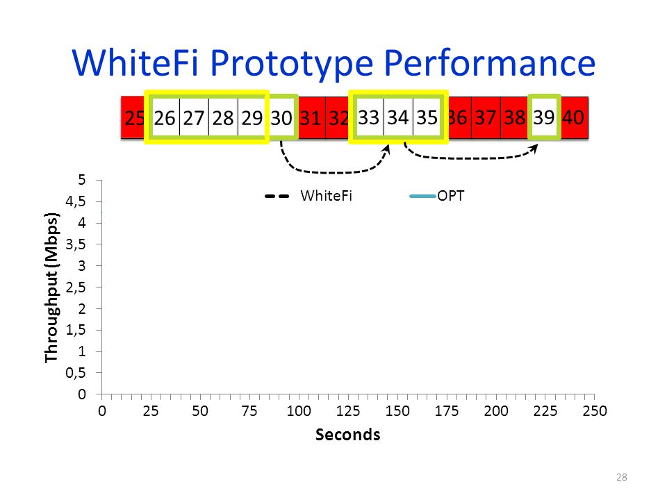
WhiteFi Prototype Performance
25 26 27 28 29 30 33 34 35 36 37 38 39 40 31 32
29
Accounting for Spatial Variation
1 2 3 4 5 1 2 3 4 5 1 2 3 4 5 = 1 2 3 4 5

30
White-Fi: Local Spectrum Asymmetry (LSA)
Indoor MIC usage on campus is problematic prevents clients in local neighborhood from using this channel Base station and associated clients do not see same spectrum as being available!

31
White-Fi: Impact of LSA
All-on-One protocol: All clients associated to same AP must be on same channel (e.g., Wi-Fi) All-on-One protocols are inherently bad in the face of LSA White-Fi deployment uses new TDMA-based MAC Serve different clients on different channels Optimally cluster clients onto few channels to 1) minimize switching cost and 2) maximize spectrum diversity
 All-on-One protocols are inherently bad in the face of LSA. White-Fi deployment uses new TDMA-based MAC. Serve different clients on different channels. Optimally cluster clients onto few channels to 1) minimize switching cost and 2) maximize spectrum diversity.")
32
System Design Hardware design Determining white spaces
Base station placement Channel assignment Dealing with wireless mics Security, discovery, …

33
MIC Protection is Super Conservative
MICs are narrowband devices However, the FCC and regulations worldwide reserve an entire TV channel for a wireless MIC

34
Impact of White Space Interference
Measure PESQ value for recorded speech Anechoic Chamber 1. PC Output to Speakers 2. MIC Recording to Computer White Space Device (WSD) Faraday Cage 3. Control interference from WSD Attenuator MIC Receiver
 Faraday Cage. 3. Control interference. from WSD. Attenuator. MIC Receiver.")
35
Some Results Time: Even short packets (16 µs) every 500 ms cause audible interference Power: No interference when received power was below squelch tones Frequency: Number of subcarriers to suppress depends on distance from MIC receiver

36
Which frequencies to suppress?
Possible Solutions: WSDs sense for MICs at very low thresholds Extremely difficult to get right, very expensive MICs reserve center frequency in the DB Will still have to be conservative Our Approach: New device at MIC receiver signals when receiver is likely to face interference When WSD interference is greater than squelch tones

37
SEISMIC System Overview
MicProtector – placed near mic receiver Enables interference detection at the mic receiver Notifies WSD of impending disruption to audio Leverages understanding gained from measurements MicProtector White Space Device Mic Receiver Mic

38
MicProtector Design Implements three key components:
Interference Detection: estimated in control bands Interference Protection: monitors squelch & noise Impending Interference Notification: strobe signals Control Band Strobe (on-symbol) Control Band Interference Level Amplitude Protection Threshold Frequency 25KHz 25KHz
 Control. Band. Interference. Level. Amplitude. Protection Threshold. Frequency. 25KHz. 25KHz.")
39
Strobing Strobes convey: impending audio disruption, mic operational band & center frequency Similar to Morse-code and on/off-keying (OOK) Quickly introduce/remove power in a pattern Only requires simple power generation/detection Amplitude Frequency

40
MicProtector Strobes the WSD for interference near threshold
SEISMIC Protocol WSD: sends short probes with increasing TX power, suppresses frequency when strobed. MicProtector: monitors interference and strobes WSD if the power in the band reaches threshold. Pkts: Probe Strobe Convergence To Coexistence MicProtector Strobes the WSD for interference near threshold MicProt. WSD 125 125 Increase in Power 50 75 100 125 25 50 Time Suppressed Frequency (KHz)
")
41
SEISMIC Evaluation

42
White-Fi: Press

43
WhiteFi: Impact on Regulatory Bodies
Radiocommunication Sector India Oct. 22, 2009 Federal Communications Commission, USA (FCC), Apr. 28 & Aug. 14, 2010 China Jan. 11, 2010 Singapore Apr. 8, 2010 Brazil (Feb. 2, 2010) Standards Industry Partners Jan. 5, 2010 Fisher Communications Inc. Jan. 14, 2010
, Apr. 28 & Aug. 14, China. Jan. 11, Singapore. Apr. 8, Brazil. (Feb. 2, 2010) Standards. Industry Partners. Jan. 5, Fisher Communications Inc. Jan. 14,")
44
White-Fi & Broadcast TV
TV broadcasters opposed to white space networking Hillary Clinton lobbying for broadcasters against White-Fi Our system demonstrated that we can reuse unused spectrum without hurting broadcasters KOMO (Ch. 38) KIRO (Ch. 39) White-Fi (Ch. 40)
 KIRO (Ch. 39) White-Fi (Ch. 40)")
45
Summary & On-going Work
White Spaces enable new networking scenarios KNOWS project researched networking problems: Spectrum assignment: MCham, LSA Spectrum efficiency: MIC Coexistence Network Agility: Using geo-location database Ongoing work: MIC sensing, mesh networks, co-existence among white space networks, …

46
Questions

48
Shuttle Deployment World’s first urban white space network!
Goal: Provide free Wi-Fi Corpnet access in MS shuttles Use white spaces as backhaul, Wi-Fi inside shuttle Obtained FCC Experimental license for MS Campus Deployed antenna on rooftop, radio in building & shuttle Protect TVs and mics using geo-location service & sensing

49
Outline Networking in TV Bands KNOWS Platform – the hardware
CMAC – the MAC protocol B-SMART – spectrum sharing algorithm Future directions and conclusions

50
MAC Layer Challenges Crucial challenge from networking point of view:
How should nodes share the spectrum? Which spectrum-band should two cognitive radios use for transmission? Channel-width…? Frequency…? Duration…? Determines network throughput and overall spectrum utilization! We need a protocol that efficiently allocates time-spectrum blocks in the space!

51
Allocating Time-Spectrum Blocks
View of a node v: Primary users Frequency f+f f Time t t+t Node v’s time-spectrum block Neighboring nodes’ time-spectrum blocks Time-Spectrum Block Within a time-spectrum block, any MAC and/or communication protocol can be used ACK ACK ACK

52
Context and Related Work
Single-channel IEEE MAC allocates on time blocks Multi-channel Time-spectrum blocks have fixed channel-width Cognitive channels with variable channel-width! time Multi-Channel MAC-Protocols: [SSCH, Mobicom 2004], [MMAC, Mobihoc 2004], [DCA I-SPAN 2000], [xRDT, SECON 2006], etc… Existing theoretical or practical work does not consider channel-width as a tunable parameter! MAC-layer protocols for Cognitive Radio Networks: [Zhao et al, DySpan 2005], [Ma et al, DySpan 2005], etc… Regulate communication of nodes on fixed channel widths

53
CMAC Overview Use common control channel (CCC) [900 MHz band]
Contend for spectrum access Reserve time-spectrum block Exchange spectrum availability information (use scanner to listen to CCC while transmitting) Maintain reserved time-spectrum blocks Overhear neighboring node’s control packets Generate 2D view of time-spectrum block reservations
![CMAC Overview Use common control channel (CCC) [900 MHz band]](http://slideplayer.com/slide/1641136/7/images/53/CMAC+Overview+Use+common+control+channel+%28CCC%29+%5B900+MHz+band%5D.jpg "Contend for spectrum access. Reserve time-spectrum block. Exchange spectrum availability information. (use scanner to listen to CCC while transmitting) Maintain reserved time-spectrum blocks. Overhear neighboring node’s control packets. Generate 2D view of time-spectrum block reservations.")
54
CMAC Overview RTS CTS DTS Indicates intention for transmitting
Contains suggestions for available time- spectrum block (b-SMART) CTS Spectrum selection (received-based) (f,f, t, t) of selected time-spectrum block DTS Data Transmission reServation Announces reserved time-spectrum block to neighbors of sender Sender Receiver RTS CTS DTS Waiting Time t DATA ACK DATA Time-Spectrum Block ACK DATA ACK t+t
 CTS. Spectrum selection (received-based) (f,f, t, t) of selected time-spectrum block. DTS. Data Transmission reServation. Announces reserved time-spectrum block to neighbors of sender. Sender. Receiver. RTS. CTS. DTS. Waiting Time. t. DATA. ACK. DATA. Time-Spectrum Block. ACK. DATA. ACK. t+t.")
55
Network Allocation Matrix (NAM)
Nodes record info for reserved time-spectrum blocks Time-spectrum block Frequency Control channel IEEE like Congestion resolution Time The above depicts an ideal scenario 1) Primary users (fragmentation) 2) In multi-hop neighbors have different views
 Primary users (fragmentation) 2) In multi-hop neighbors have different views.")
56
Network Allocation Matrix (NAM)
Nodes record info for reserved time-spectrum blocks Primary Users Frequency Control channel IEEE like Congestion resolution Time The above depicts an ideal scenario 1) Primary users (fragmentation) 2) In multi-hop neighbors have different views
 Primary users (fragmentation) 2) In multi-hop neighbors have different views.")
57
More congestion on control channel
B-SMART Which time-spectrum block should be reserved…? How long…? How wide…? B-SMART (distributed spectrum allocation over white spaces) Design Principles B: Total available spectrum N: Number of disjoint flows 1. Try to assign each flow blocks of bandwidth B/N 2. Choose optimal transmission duration t Long blocks: Higher delay Short blocks: More congestion on control channel
 Design Principles. B: Total available spectrum. N: Number of disjoint flows. 1. Try to assign each flow blocks of bandwidth B/N. 2. Choose optimal transmission duration t. Long blocks: Higher delay. Short blocks: More congestion on control channel.")
58
B-SMART Upper bound Tmax~10ms on maximum block duration
Nodes always try to send for Tmax 1. Find smallest bandwidth b for which current queue-length is sufficient to fill block b Tmax b b=B/N Tmax Tmax 2. If b ≥ B/N then b := B/N 3. Find placement of bxt block that minimizes finishing time and does not overlap with any other block 4. If no such block can be placed due prohibited bands then b := b/2

59
Example Number of valid reservations in NAM estimate for N
Case study: 8 backlogged single-hop flows Tmax 80MHz 2(N=2) 4 (N=4) 8 (N=8) 2 (N=8) 5(N=5) 1 (N=8) 40MHz 3 (N=8) 1 (N=1) 3 (N=3) 7(N=7) 6 (N=6) 1 2 3 4 5 6 7 8 1 2 3 Time
 4 (N=4) 8 (N=8) 2 (N=8) 5(N=5) 1 (N=8) 40MHz. 3 (N=8) 1 (N=1) 3 (N=3) 7(N=7) 6 (N=6) Time.")
60
B-SMART How to select an ideal Tmax…?
Let be maximum number of disjoint channels (with minimal channel-width) We define Tmax:= T0 We estimate N by #reservations in NAM based on up-to-date information adaptive! We can also handle flows with different demands (only add queue length to RTS, CTS packets!) TO: Average time spent on one successful handshake on control channel Prevents control channel from becoming a bottleneck! Nodes return to control channel slower than handshakes are completed
 We define Tmax:= T0. We estimate N by #reservations in NAM. based on up-to-date information adaptive! We can also handle flows with different demands. (only add queue length to RTS, CTS packets!) TO: Average time spent on one successful handshake on control channel. Prevents control channel. from becoming a bottleneck! Nodes return to control. channel slower than. handshakes are completed.")
61
Provides strong validation for our choice of Tmax
Performance Analysis In the paper only… Markov-based performance model for CMAC/B-SMART Captures randomized back-off on control channel B-SMART spectrum allocation We derive saturation throughput for various parameters Does the control channel become a bottleneck…? If so, at what number of users…? Impact of Tmax and other protocol parameters Analytical results closely match simulated results Even for large number of flows, control channel can be prevented from becoming a bottleneck Provides strong validation for our choice of Tmax

62
Simulation Results - Summary
Simulations in QualNet Various traffic patterns, mobility models, topologies B-SMART in fragmented spectrum: When #flows small total throughput increases with #flows When #flows large total throughput degrades very slowly B-SMART with various traffic patterns: Adapts very well to high and moderate load traffic patterns With a large number of very low-load flows performance degrades ( Control channel)
")
63
KNOWS in Mesh Networks b-SMART finds the best allocation!
More in the paper… Aggregate Throughput of Disjoint UDP flows Throughput (Mbps) b-SMART finds the best allocation! # of flows
 b-SMART finds the best allocation! # of flows.")
64
Summary White Spaces overcome shortcoming of Wi-Fi
Possible to build hardware that does not interfere with TV transmissions CMAC uses control channel to coordinate among nodes B-SMART efficiently utilizes available spectrum by using variable channel widths

65
Future Work & Open Problems
Integrate B-SMART into KNOWS Address control channel vulnerability Design AP-based networks Build, demonstrate large mesh network!

66
Other Ongoing Projects
Network Management DAIR: Managing enterprise wireless networks Sherlock: localizing performance failures eXpose: mining for communication rules in a packet trace Green Computing Cell2Notify: reducing battery consumption of mobile phones Somniloquy: enabling network connectivity to sleeping PCs

67
WhiteFi System Challenges
Fragmentation Spatial Variation Temporal Variation Impact Discovery Spectrum Assignment -Stress, Wi-Fi load may vary but that is not the same as fragmentation -I will soon demonstrate to you how these differences raise new challenges Disconnection

68
Discovering a Base Station
Discovery Problem Goal Quickly find channels BS is using 1 2 3 4 5 1 2 3 4 5 Discovery Time = (B x W) -What is the worst case discovery time? Can we optimize this discovery time? BS and Clients must use same channels How does the new client discover channels used by the BS? Fragmentation Try different center channel and widths
 -What is the worst case discovery time Can we optimize this discovery time BS and Clients must use same channels. How does the new client discover channels used by the BS Fragmentation. Try different center channel and widths.")
69
Whitespaces Platform: Adding SIFT
PC Scanner (SDR) Net Stack TV/MIC detection FFT FPGA UHF RX Daughterboard Temporal Analysis (SIFT) Whitespace Radios Connection Manager Wi-Fi Card UHF Translator Atheros Device Driver SIFT: Signal Interpretation before Fourier Transform
 Net. Stack. TV/MIC detection. FFT. FPGA. UHF RX Daughterboard. Temporal Analysis. (SIFT) Whitespace Radios. Connection Manager. Wi-Fi Card. UHF. Translator. Atheros Device Driver. SIFT: Signal Interpretation before Fourier Transform.")
70
Does not decode packets Pattern match in time domain
SIFT, by example 5 MHz 10 MHz ADC SIFT SIFT Data ACK SIFS Beacon Does not decode packets Amplitude Pattern match in time domain Time

71
BS Discovery: Optimizing with SIFT
1 2 3 4 5 1 2 3 4 5 18 MHz -SIFT: jump cleverly until we hit the “sweet” spot. Time Amplitude Matched against 18 MHz packet signature SIFT enables faster discovery algorithms

72
BS Discovery: Optimizing with SIFT
Linear SIFT (L-SIFT) 1 2 3 4 5 Jump SIFT (J-SIFT) 1 2 3 4 5 6 7 8
 Jump SIFT (J-SIFT)")
73
Discovery: Comparison to Baseline
Baseline =(B x W) L-SIFT = (B/W) J-SIFT = (B/W) 2X reduction
 L-SIFT = (B/W) J-SIFT = (B/W) 2X reduction.")
74
WhiteFi System Challenges
Fragmentation Spatial Variation Temporal Variation Impact Discovery Spectrum Assignment -Stress, Wi-Fi load may vary but that is not the same as fragmentation -I will soon demonstrate to you how these differences raise new challenges Disconnection

75
Operating in TV Bands DSP Routines detect TV presence Scanner
UHF Translator Wireless Card Set channel for data communication Modify driver to operate in MHz Transmission in the TV Band

76
KNOWS: Salient Features
Prototype has transceiver and scanner Use scanner as receiver when not scanning Scanner Antenna Data Transceiver Antenna

77
KNOWS Platform: Salient Features
Can dynamically adjust channel-width and center-frequency. Low time overhead for switching can change at fine-grained time-scale Transceiver can tune to contiguous spectrum bands only! Frequency

78
Changing Channel Widths
Scheme 1: Turn off certain subcarriers ~ OFDMA 10 MHz 20 MHz Issues: Guard band? Pilot tones? Modulation scheme?

79
Changing Channel Widths
Scheme 2: reduce subcarrier spacing and width! Increase symbol interval 10 MHz 20 MHz Properties: same # of subcarriers, same modulation

80
Adaptive Channel-Width
20Mhz 5Mhz Why is this a good thing…? Fragmentation White spaces may have different sizes Make use of narrow white spaces if necessary Opportunistic, load-aware channel allocation Few nodes: Give them wider bands! Many nodes: Partition the spectrum in narrower bands Frequency

81
Version 2: WhiteFi System
Prototype Hardware Platform Base Stations and Clients Algorithms Discovery Spectrum Assignment and Implementation -Key point: we have thought through the MAIN issues that arise due to these differences and we address them -This it the FIRST whitespaces based wirelss network -We do NOT address sensing. We leverage significant prior work on sensing. Handling Disconnections Evaluation Deployment of prototype nodes Simulations

82
WhiteFi System Challenges
Fragmentation Spatial Variation Temporal Variation Impact Discovery Spectrum Assignment -Stress, Wi-Fi load may vary but that is not the same as fragmentation -I will soon demonstrate to you how these differences raise new challenges Disconnection

83
MSR KNOWS Program Prototypes
Version 1: Ad hoc networking in white spaces Capable of sensing TV signals, limited hardware functionality, analysis of design through simulations Version 2: Infrastructure based networking (WhiteFi) Capable of sensing TV signals & microphones, deployed in lab Version 3: Campus-wide backbone network (WhiteFi + Geolocation) Deployed on campus, and provide coverage in MS Shuttles
 Capable of sensing TV signals & microphones, deployed in lab. Version 3: Campus-wide backbone network (WhiteFi + Geolocation) Deployed on campus, and provide coverage in MS Shuttles.")
84
White-Fi: Deployment Implemented and deployed the world’s first operational white space network on Microsoft Redmond campus (Oct. 16, 2009) White Space Network Setup Shuttle Deployment WS Antenna WS Antenna on MS Shuttle Data packets over UHF

85
White-Fi: Deployment Implemented and deployed the world’s first operational white space network on Microsoft Redmond campus (Oct. 16, 2009) FCC experimental license Provide Internet connectivity in shuttle buses (inside bus, clients can use Wi-Fi, backhaul is White Spaces) Covering the entire campus with 3 base stations! (>1 square mile) (compare Wi-Fi: would need 100’s of Aps) (compare cellular: not free) Protecting wireless microphones using a geo-location database Adaptive channel width Dynamic channel selection
 Covering the entire campus with 3 base stations! (>1 square mile) (compare Wi-Fi: would need 100’s of Aps) (compare cellular: not free) Protecting wireless microphones using a geo-location database. Adaptive channel width. Dynamic channel selection.")
86
White-Fi: Deployment The first white space network in the world
Implemented and deployed the world’s first operational white space network on Microsoft Redmond campus (Oct. 16, 2009) FCC experimental license Provide Internet connectivity in shuttle buses (inside bus, clients can use Wi-Fi, backhaul is White Spaces) Covering the entire campus with 3 base stations! (>1 square mile) (compare Wi-Fi: would need 100’s of Aps) (compare cellular: not free) Protecting wireless microphones using a geo-location database Adaptive channel width Dynamic channel selection The first white space network in the world The first opportunistic (cognitive) network in the world
 FCC experimental license. Provide Internet connectivity in shuttle buses (inside bus, clients can use Wi-Fi, backhaul is White Spaces) Covering the entire campus with 3 base stations! (>1 square mile) (compare Wi-Fi: would need 100’s of Aps) (compare cellular: not free) Protecting wireless microphones using a geo-location database. Adaptive channel width. Dynamic channel selection. The first white space network in the world. The first opportunistic (cognitive) network in. the world.")
Similar presentations


 High-Speed LANs. 2 Introduction Fast Ethernet and Gigabit Ethernet Fast Ethernet and Gigabit Ethernet Fibre Channel Fibre Channel High-speed.>")

 1 Chapter 11 Information.>")
 1 Chapter 12 Cross-Layer.>")


 Joint work with Hari Balakrishnan.>")


 Defence R&D Canada – Ottawa 1 Properties of Mobile Tactical Radio Networks on VHF Bands Li Li & Phil Vigneron Communications.>")

