Download presentation
Presentation is loading. Please wait.

1
Basic Concepts in Ductile Detailing
of Steel Structures EAC 2013 Michael D. Engelhardt University of Texas at Austin

2
Overview of Presentation
What is Ductility ? Why is Ductility Important ? How Do We Achieve Ductility in Steel Structures ? Ductility in Seismic-Resistant Design

3
Ductility = inelastic deformation capacity
What is Ductility ? Ductility: The ability to sustain large inelastic deformations without significant loss in strength. Ductility = inelastic deformation capacity Ductility: - material response - structural component response (members and connections) - global frame response
 - global frame response.")
4
F Δ Ductility F Fyield Δ

5
How is ductility developed in steel structures ?
F Δ Ductility = Yielding F Loss of load carrying capability: Instability Fracture Δ

6
Why is Ductility Important?
Permits redistribution of internal stresses and forces Increases strength of members, connections and structures Permits design based on simple equilibrium models Results in more robust structures Provides warning of failure Permits structure to survive severe earthquake loading

7
Why Ductility ? Permits redistribution of internal stresses and forces
Increases strength of members, connections and structures Permits design based on simple equilibrium models Results in more robust structures Provides warning of failure Permits structure to survive severe earthquake loading

8
General Philosophy for Earthquake-Resistant Design
Objective: Prevent loss of life by preventing collapse in the extreme earthquake likely to occur at a building site. Objectives are not to: - limit damage - maintain function - provide for easy repair Design Approach: Survive earthquake by providing large ductility rather than large strength

9
H Δ H Helastic Available Ductility Required Strength 3/4 *Helastic
MAX

10
H Δ H Helastic Observations: We can trade strength for ductility
MAX

11
H Δ H Helastic Observations: Ductility = Damage 3/4 *Helastic
MAX

12
H Δ H Helastic Observations:
The maximum lateral load a structure will see in an earthquake is equal to the lateral strength of the structure 1/4 *Helastic MAX

13
How Do We Achieve Ductility in Steel Structures ?

14
Ductile Limit States Must Precede Brittle Limit States
Achieving Ductile Response.... Ductile Limit States Must Precede Brittle Limit States

15
Example P P gusset plate double angle tension member
Ductile Limit State: Gross-section yielding of tension member Brittle Limit States: Net-section fracture of tension member Block-shear fracture of tension member Net-section fracture of gusset plate Block-shear fracture of gusset plate Bolt shear fracture Plate bearing failure in double angles or gusset

16
double angle tension member
P P Example: Gross-section yielding of tension member must precede net section fracture of tension member Gross-section yield: Pyield = Ag Fy Net-section fracture: Pfracture = Ae Fu

17
P P Pyield Pfracture Ag Fy Ae Fu double angle tension member
The required strength for brittle limit states is defined by the capacity of the ductile element Pyield Pfracture Ag Fy Ae Fu Steels with a low yield ratio are preferable for ductile behavior = yield ratio

18
double angle tension member
P P Example: Gross-section yielding of tension member must precede bolt shear fracture Gross-section yield: Pyield = Ag Fy Bolt shear fracture: Pbolt-fracture = nb ns Ab Fv

19
Pyield Pbolt-fracture
double angle tension member P P The required strength for brittle limit states is defined by the capacity of the ductile element Pyield Pbolt-fracture The ductile element must be the weakest element in the load path

20
P P Example: Bolts: 3 - 3/4" A325-X double shear
double angle tension member P P Example: Bolts: /4" A325-X double shear Ab = 0.44 in2 Fv = x 120 ksi = 68 ksi Pbolt-fracture = 3 x 0.44 in2 x 68 ksi x 2 = 180k Angles: 2L 4 x 4 x 1/4 A36 Ag = 3.87 in2 Pyield = 3.87 in2 x 36 ksi = 139k

21
Pyield Pbolt-fracture
double angle tension member P P Pyield Pbolt-fracture Pyield = 139k Pbolt-fracture = 180k OK What if the actual yield stress for the A36 angles is greater than 36 ksi? Say, for example, the actual yield stress for the A36 angle is 54 ksi.

22
Pyield Pbolt-fracture Pyield Pbolt-fracture
double angle tension member P P Pyield Pbolt-fracture Pyield = 3.87 in2 x 54 ksi = 209k Pbolt-fracture = 180k Pyield Pbolt-fracture Bolt fracture will occur before yield of angles non-ductile behavior

23
P P Pyield Pbrittle Stronger is not better in the ductile element
double angle tension member P P Pyield Pbrittle Stronger is not better in the ductile element (Ductile element must be weakest element in the load path) For ductile response: must consider material overstrength in ductile element
 For ductile response: must consider material overstrength in ductile element.")
24
P P Pyield Pbrittle Pyield = Ag RyFy
double angle tension member P P Pyield Pbrittle The required strength for brittle limit states is defined by the expected capacity of the ductile element (not minimum specified capacity) Pyield = Ag RyFy Ry Fy = expected yield stress of angles
 Pyield = Ag RyFy. Ry Fy = expected yield stress of angles.")
25
Ductile Limit States Must Precede Brittle Limit States
Achieving Ductile Response.... Ductile Limit States Must Precede Brittle Limit States Define the required strength for brittle limit states based on the expected yield capacity of ductile element The ductile element must be the weakest in the load path Unanticipated overstrength in the ductile element can lead to non-ductile behavior. Steels with a low value of yield ratio, Fy / Fu are preferable for ductile elements

26
Connection response is generally non-ductile.....
Achieving Ductile Response.... Connection response is generally non-ductile..... Connections should be stronger than connected members

32
Be cautious of high-strength steels
Achieving Ductile Response.... Be cautious of high-strength steels

33
Ref: Salmon and Johnson - Steel Structures: Design and Behavior
General Trends: As Fy Elongation (material ductility) Fy / Fu Ref: Salmon and Johnson - Steel Structures: Design and Behavior
 Fy / Fu. Ref: Salmon and Johnson - Steel Structures: Design and Behavior.")
34
Be cautious of high-strength steels
Achieving Ductile Response.... Be cautious of high-strength steels High strength steels are generally less ductile (lower elongations) and generally have a higher yield ratio. High strength steels are generally undesirable for ductile elements
 and generally have a higher yield ratio. High strength steels are generally undesirable for ductile elements.")
35
Achieving Ductile Response....
Use Sections with Low Width-Thickness Ratios and Adequate Lateral Bracing

36
M q Effect of Local Buckling on Flexural Strength and Ductility Mp
Increasing b / t

37
Mp Moment Capacity Ductility Plastic Buckling Inelastic Buckling
0.7 My Elastic Buckling hd p Width-Thickness Ratio (b/t) r Ductility
 r. Ductility.")
38
Mp Moment Capacity Ductility Plastic Buckling Inelastic Buckling
0.7 My Elastic Buckling Slender Element Sections hd p Width-Thickness Ratio (b/t) r Ductility
 r. Ductility.")
39
Mp Moment Capacity Ductility Plastic Buckling Inelastic Buckling
0.7 My Elastic Buckling Noncompact Sections hd p Width-Thickness Ratio (b/t) r Ductility
 r. Ductility.")
40
Mp Moment Capacity Ductility Plastic Buckling Inelastic Buckling
0.7 My Elastic Buckling Compact Sections hd p Width-Thickness Ratio (b/t) r Ductility
 r. Ductility.")
41
Mp Moment Capacity Ductility Plastic Buckling Inelastic Buckling
0.7 My Elastic Buckling Highly Ductile Sections (for seismic design) hd p Width-Thickness Ratio (b/t) r Ductility
 hd. p. Width-Thickness Ratio (b/t) r. Ductility.")
42
Local buckling of noncompact and slender element sections

43
Local buckling of moment frame beam with highly ductile compactness ( < hd ) .....
 .....")
45
Local buckling of a shear yielding EBF link with highly ductile compactness ( < hd ) .....
 .....")
47
Effect of Local Buckling on Ductility
For highly ductile flexural response: b f t h w Example: W-Shape

48
Beam Flanges Beam Web Highly Ductile Compactness:

49
Lateral Torsional Buckling
Lateral torsional buckling controlled by: Lb = distance between beam lateral braces ry = weak axis radius of gyration Beam lateral braces Lb Lb

50
Effect of Lateral Torsional Buckling on Flexural Strength and Ductility:
M M q Mp Increasing Lb / ry

52
Effect of Lateral Buckling on Ductility
For highly ductile flexural response: For Fy = 50 ksi:

53
Recognize that buckling of a compression member is non-ductile
Achieving Ductile Response.... Recognize that buckling of a compression member is non-ductile

54
Pcr P d P Pcr d

55
Experimental Behavior of Brace Under Cyclic Axial Loading
W6x20 Kl/r = 80 P

56
How Do We Achieve Ductile Response in Steel Structures ?
Ductile limit states must precede brittle limit states Ductile elements must be the weakest in the load path Stronger is not better in ductile elements Define Required Strength for brittle limit states based on expected yield capacity of ductile element Provide connections that are stronger than members Avoid high strength steels in ductile elements Use cross-sections with low b/t ratios Provide adequate lateral bracing Recognize that compression member buckling is non-ductile

57
How Do We Achieve Ductile Response in Steel Structures ?

58
Ductile Detailing for Seismic Resistance
High Ductility Steel Systems for Lateral Resistance: Special Moment Frames Special Concentrically Braced Frames Eccentrically Braced Frames Buckling Restrained Braced Frames Special Plate Shear Walls

59
Ductile Detailing for Seismic Resistance
Choose frame elements ("fuses") that will yield in an earthquake. Detail "fuses" to sustain large inelastic deformations prior to the onset of fracture or instability (i.e. , detail fuses for ductility). Design all other frame elements to be stronger than the fuses, i.e., design all other frame elements to develop the capacity of the fuses.
 that will yield in an earthquake. Detail fuses to sustain large inelastic deformations prior to the onset of fracture or instability (i.e. , detail fuses for ductility). Design all other frame elements to be stronger than the fuses, i.e., design all other frame elements to develop the capacity of the fuses.")
60
Special Moment Frame (SMF)
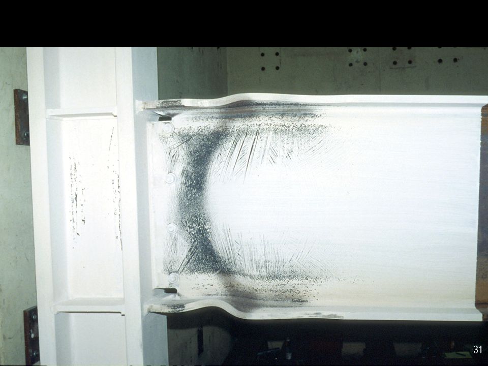
Ductile fuse: Flexural yielding of beams

61
Inelastic Response of a Special Moment Frame
Fuse: Flexural Yielding of Beams Detail beam for ductile flexural response: no high strength steels low b/t ratios (highly ductile ) beam lateral bracing (per seismic req'ts)
 beam lateral bracing (per seismic req ts)")
62
Inelastic Response of a Special Moment Frame
Design all other frame elements to be stronger than the beam: Connections Beam-to-column connections Column splices Column bases Column buckling capacity Column flexural capacity

64
Special Concentrically Braced Frame
Ductile fuse: tension yielding of braces.

65
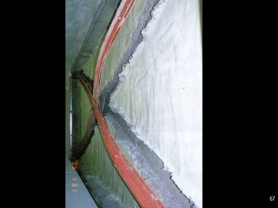
Inelastic Response of an SCBF
Tension Brace: Yields (ductile) Compression Brace: Buckles (nonductile)
 Compression Brace: Buckles (nonductile)")
66
Inelastic Response of CBFs under Earthquake Loading
Compression Brace (previously in tension): Buckles (nonductile) Tension Brace (previously buckled in compression): Yields (ductile) Connections, columns and beams: designed to be stronger than braces
: Buckles (nonductile) Tension Brace (previously buckled in compression): Yields (ductile) Connections, columns and beams: designed to be stronger than braces.")
69
An X-braced CBF with wide flange braces that have buckled in-plane.
Note that depending on the orientation of the bracing member and the end connection details, braces may buckle either in-plane or out-of-plane.

70
Eccentrically Braced Frames (EBFs)
Ductile fuse: Shear yielding of links Eccentrically Braced Frames (EBFs) are braced frames, consisting of beams, columns, and braces. Unlike conventional concentrically braced frames, an intentional eccentricity is introduced in EBFs, so that the brace-beam-column centerlines do not meet at a single point. The framing is arranged so as to isolate a short segment of beam at one of each brace. This isolated beam segment is called a "link." EBFs are designed so that inelastic action occurs within the links. The links, in turn, can be designed and detailed to provide very high levels of ductility. The braces, columns and beam segments outside of the links are designed to remain essentially elastic, by designing these elements to be stronger than the links. A well designed EBF can combine high stiffness in the elastic range (similar to a concentrically braced frame), with high ductility in the inelastic range (similar to a moment resisting frame). Because of the high elastic stiffness of an EBF, beam and column sizes are generally much smaller than in a moment resisting frame.
 are braced frames, consisting of beams, columns, and braces. Unlike conventional concentrically braced frames, an intentional eccentricity is introduced in EBFs, so that the brace-beam-column centerlines do not meet at a single point. The framing is arranged so as to isolate a short segment of beam at one of each brace. This isolated beam segment is called a link. EBFs are designed so that inelastic action occurs within the links. The links, in turn, can be designed and detailed to provide very high levels of ductility. The braces, columns and beam segments outside of the links are designed to remain essentially elastic, by designing these elements to be stronger than the links. A well designed EBF can combine high stiffness in the elastic range (similar to a concentrically braced frame), with high ductility in the inelastic range (similar to a moment resisting frame). Because of the high elastic stiffness of an EBF, beam and column sizes are generally much smaller than in a moment resisting frame.")
71
Link Link

72
Inelastic Response of an EBF

74
Braces, beam segments outside of link, columns, connections: designed to be stronger than link

75
Buckling-Restrained Braced Frames (BRBFs)
Ductile fuse: Tension yielding and compression yielding of Buckling Restrained Braces

76
Buckling- Restrained Brace: Steel Core + Casing

77
Buckling- Restrained Brace: Steel Core + Casing
Steel jacket Mortar Debonding material Section A-A

78
Inelastic Response of BRBFs

79
Tension Brace: Yields Compression Brace: Yields

80
Compression Brace: Yields
Tension Brace: Yields Connections, columns and beams: designed to be stronger than braces

81
Special Plate Shear Walls (SPSW)
Ductile fuse: Tension field yielding of web panels

82
Inelastic Response of a SPSW
Development yielding along tension diagonals Shear buckling Columns, beams and connections: designed to be stronger than web panel

83
Ductile Fuses: Special Moment Frames: Beams: Flexural Yielding
Special Concentrically Braced Frames: Braces: Tension Yielding Eccentrically Braced Frames: Links: Shear Yielding Buckling Restrained Braced Frames: Braces: Tension and Compression Yielding Special Plate Shear Walls: Web Panels: Tension Field Yielding

84
Summary Ductility = Inelastic Deformation Capacity
Ductility Important in all Structures Ductility Key Element of Seismic Resistance

85
Summary Achieving Ductility - Simple Rules.........
avoid high strength steels use sections with low b/t's and adequate lateral bracing design connections and other brittle elements to be stronger than ductile members For seismic-resistant structures: Follow AISC Seismic Provisions

Similar presentations


 Grants Chapter 6.>")
