Download presentation
Presentation is loading. Please wait.

1
INTERFERENCE

2
BE-PHYSICS- INTERFERENCE-2010-11
Topics Two source interference Double-slit interference Coherence Intensity in double slit interference Interference from thin film Michelson’s Interferometer Text Book: PHYSICS VOL 2 by Halliday, Resnick and Krane (5th Edition) MIT-MANIPAL BE-PHYSICS- INTERFERENCE
 MIT-MANIPAL. BE-PHYSICS- INTERFERENCE")
3
What is an Electromagnetic wave (EM)?
900 Electric field (E) Magnetic field (B) The electromagnetic waves consist of the electric and magnetic field oscillations. In the electromagnetic waves, electric field is perpendicular to the magnetic field and both are perpendicular to the direction of propagation of the waves.
 Magnetic field (B) The electromagnetic waves consist of the electric and magnetic field oscillations. In the electromagnetic waves, electric field is perpendicular to the magnetic field and both are perpendicular to the direction of propagation of the waves.")
4
Radio and television Waves
Properties of electromagnetic waves (EM) Electromagnetic waves are non-mechanical waves i.e they do not require material medium for propagation. They are transverse waves. ie. They travel in the form of ‘crests’ and ‘troughs’. Examples: Light waves Heat waves Radio and television Waves Ultraviolet waves Gamma rays, X- rays
 Electromagnetic waves are non-mechanical waves i.e they do not require material medium for propagation. They are transverse waves. ie. They travel in the form of ‘crests’ and ‘troughs’. Examples: Light waves. Heat waves. Radio and television Waves. Ultraviolet waves. Gamma rays, X- rays.")
5
They differ from each other in wavelength (λ) and frequency (f).
In vacuum, all electromagnetic waves (EM) move at the same speed and differ from one another in their frequency (f). Speed=c=Frequency x wavelength i.e c= f x λ c= 3 x 10⁸ m/s
 move at the same speed and differ from one another in their frequency (f). Speed=c=Frequency x wavelength. i.e c= f x λ. c= 3 x 10⁸ m/s.")
6
Electromagnetic spectrum
Name Frequency range (Hz) Wavelength range Gamma rays(γ-rays) 5 x x 1019 nm X-rays 3 x x 1016 0.1 nm-30nm Ultraviolet light 1 x x 1014 30nm-400nm Visible light 8 x x 1014 400nm-800nm Infra-red 4 x x 1013 800nm-30000nm Radio frequencies 3 x x 104 nm More frequency (f) more energy (E), and lesser wavelength(λ).
 Wavelength range. Gamma rays(γ-rays) 5 x x nm. X-rays. 3 x x nm-30nm. Ultraviolet light. 1 x x nm-400nm. Visible light. 8 x x nm-800nm. Infra-red. 4 x x nm-30000nm. Radio frequencies. 3 x x nm. More frequency (f) more energy (E), and lesser wavelength(λ).")
7
Dual Nature of Light Albert Einstein proposed that light not only behaves as a wave, but as a particle too. Light is a particle in addition to a wave-Dual nature of light. Light as a stream of particles Dual nature of light -treated as 1) a wave or 2) as a particle Dual nature of light successfully explains all the phenomena connected with light.
 a wave or. 2) as a particle. Dual nature of light successfully explains all the phenomena connected with light.")
8
When light behaves as a Wave?
f The wave nature of light dominates when light interacts with light. The wave nature of light explains the following properties of light: Refraction of light Reflection of light Interference of light Diffraction of light Polarization light

9
When light behaves as a stream of particles?
The particle nature of light dominates when the light interacts with matter (like solids, liquids and gases). Particle nature - Photoelectric, Compton Effect, Black body radiation.. Light as a stream of particles Quantum (bundles/packets of energy) (Photon/quantum) The light is propagated in bundles of small energy, each bundle being called a quantum. Each quantum is composed of many small particles called quanta or photon. Photon energy E = hf h = Planck’s constant = 6.626x10⁻³⁴Js f = frequency of radiation
. Particle nature - Photoelectric, Compton Effect, Black body radiation.. Light as a stream of particles. Quantum (bundles/packets of energy) (Photon/quantum) The light is propagated in bundles of small energy, each bundle being called a quantum. Each quantum is composed of many small particles called quanta or photon. Photon energy. E = hf. h = Planck’s constant = 6.626x10⁻³⁴Js. f = frequency of radiation.")
10
Energy of a photon or light wave:
Light as a wave: c= f Light as a particle: E = hf photon Energy of a photon or light wave: Where h = Planck’s constant = 6.626x10⁻³⁴Js f = frequency of a light wave - c = velocity of light λ= wavelength of a light wave -distance between successive crests

11
Visible Light 400–435 nm Violet 435 nm-440nm Indigo 440–480 nm Blue 480–530 nm Green 530–590 nm Yellow 590–630 nm Orange 630–700 nm Red The color of visible light is determined by its wavelength. White light is a mixture of all colors. We can separate out individual colors with a prism. 1 nm = 10^-9 m

12
Wave Function of Sinusoidal Waves
y(x,t) = ym sin(kx-wt) ym: amplitude kx-wt : phase k: wave number w: angular frequency
 = ym sin(kx-wt) ym: amplitude. kx-wt : phase. k: wave number. w: angular frequency.")
13
PRINCIPLE OF SUPERPOSITION
When two waves traveling almost in the same direction superpose, the resulting displacement at a given point is the algebraic sum of the individual displacements. i.e. when waves, y1=A sin ωt & y2=A sin (ωt + ) superpose, the resultant displacement is y= y1+y2= a sin (ωt) + a sin (ωt+)
 superpose, the resultant displacement is. y= y1+y2= a sin (ωt) + a sin (ωt+)")
14
INTERFERENCE OF LIGHT

15
TWO-SSOURCE INTERFERENCE
When identical waves from two sources overlap at a point in space, the combined wave intensity at that point can be greater or less than the intensity of either of the two waves. This effect is called interference. OR When two waves of same frequency (or wavelength) with zero initial phase difference or constant phase difference superimpose over each other, then the resultant amplitude (or intensity) in the region of superposition is different than the amplitude (or intensity) of individual waves.
 with zero initial phase difference or constant phase difference superimpose over each other, then the resultant amplitude (or intensity) in the region of superposition is different than the amplitude (or intensity) of individual waves.")
16
At certain points either two crests or two troughs interact giving rise to maximum amplitude resulting in maximum intensity. (Constructive interference). At certain points a crest and a trough interact giving rise to minimum or zero amplitude resulting in minimum or zero intensity. (Destructive interference).
. At certain points a crest and a trough interact giving rise to minimum or zero amplitude resulting in minimum or zero intensity. (Destructive interference).")
17
TWO-SOURCE INTERFERENCE
Constructive Interference Destructive interference Two waves (of the same wavelength) are said to be in phase if the crests (and troughs) of one wave coincide with the crests (and troughs) of the other. The net intensity of the resultant wave is greater than the individual waves. (Constructive interference). If the crest of one wave coincides with the trough of the second, they are said to be completely out of phase. The net intensity of the resultant wave is less than the individual waves. (Destructive interference).
 are said to be in phase if the crests (and troughs) of one wave coincide with the crests (and troughs) of the other. The net intensity of the resultant wave is greater than the individual waves. (Constructive interference). If the crest of one wave coincides with the trough of the second, they are said to be completely out of phase. The net intensity of the resultant wave is less than the individual waves. (Destructive interference).")
18
TWO-SOURCE INTERFERENCE
INTERFERENCE PATTERN PRODUCED BY WATER WAVES IN A RIPPLE TANK Maxima: where the shadows show the crests and valleys (or troughs). Minima: where the shadows are less clearly visible MIT-MANIPAL BE-PHYSICS- INTERFERENCE
. Minima: where the shadows are less clearly visible. MIT-MANIPAL. BE-PHYSICS- INTERFERENCE")
19
Path difference corresponds to phase difference of 2.
PHASE AND PATH DIFFERENCE Phase: Phase of a vibrating particle at any instant indicates its state of vibration. B F λ π/2 3π/2 2π π O A C 3λ/4 E G t=0 λ/4 λ/2 λ λ D Phase may be expressed in terms of angle as a fraction of 2π. Path difference corresponds to phase difference of 2.

20
Constructive interference
path difference p = 1 or phase difference =2 path difference p= 0 or phase difference = 0 General condition: Path difference p = m or phase difference = 2m where m = 0, 1, 2, 3,………… order of interference. 2λ path difference p =2 or phase difference = 4

21
Constructive interference
Maximal constructive interference of two waves occurs when their: path difference between the two waves is a whole number multiple of wavelength. OR Phase difference is 0, 2, 4 , … (the waves are in-phase).
.")
22
Path difference p=(m+1/2) phase difference =(2m+1)
DISTRUCTIVE INTERFERENCE path difference p = 3/2 or phase difference =3 path difference p= /2 phase difference = 1 General condition: Path difference p=(m+1/2) or phase difference =(2m+1) where m = 0, 1, 2, 3, ……… path difference p = 5/2 phase difference = 5
 or. phase difference =(2m+1) where m = 0, 1, 2, 3, ……… path difference p = 5/2. phase difference = 5")
23
Complete destructive interference of two waves occur when
the path difference between the two waves is an odd number multiple of half wavelength. Or the phase difference is , 3, 5, … (the waves are 180o out of phase).
.")
24
Coherence – necessary condition for interference to occur.
Two waves are called coherent when they are of : same amplitude same frequency/wavelength same phase or are at a constant phase difference

25
A SECTION OF INFINITE WAVE
COHERENCE A SECTION OF INFINITE WAVE A WAVE TRAIN OF FINITE LENGTH L For interference pattern to occur, the phase difference at point on the screen must not change with time. This is possible only when the two sources are completely coherent. No two independent sources can act as coherent sources, because the emission of light by the atoms of one source is independent of that the other. If the two sources are completely independent light sources, no fringes appear on the screen (uniform illumination). This is because the two sources are completely incoherent.
. This is because the two sources are completely incoherent.")
26
A SECTION OF INFINITE WAVE
COHERENCE A SECTION OF INFINITE WAVE A WAVE TRAIN OF FINITE LENGTH L Common sources of visible light emit light wave trains of finite length rather than an infinite wave. The degree of coherence decreases as the length of wave train decreases. MIT-MANIPAL BE-PHYSICS- INTERFERENCE

27
BE-PHYSICS- INTERFERENCE-2010-11
COHERENCE Laser light is highly coherent whereas a laboratory monochromatic light source (sodium vapor lamp) may be partially coherent. Common sources of visible light emit light wave trains of finite length rather than an infinite wave. MIT-MANIPAL BE-PHYSICS- INTERFERENCE
 may be partially coherent. Common sources of visible light emit light wave trains of finite length rather than an infinite wave. MIT-MANIPAL. BE-PHYSICS- INTERFERENCE")
28
COHERENCE Methods of producing coherent sources:
(1). Division of wave front: In this method, the wave front is divided into two or more parts with the help of mirrors, lenses and prisms. The common methods are: Young’s double slit arrangement, b. Lloyd's single mirror method. (2) Division of Amplitude: In this method, the amplitude of the incoming beam is divided into two or more parts by partial reflection with the help of mirrors, lenses and prisms. These divided parts travel different paths and finally brought together to produce interference. The common methods are Newton’s rings, b. Michelson’s interferometer.
. Division of wave front: In this method, the wave front is divided into two or more parts with the help of mirrors, lenses and prisms. The common methods are: Young’s double slit arrangement, b. Lloyd s single mirror method. (2) Division of Amplitude: In this method, the amplitude of the incoming beam is divided into two or more parts by partial reflection with the help of mirrors, lenses and prisms. These divided parts travel different paths and finally brought together to produce interference. The common methods are. Newton’s rings, b. Michelson’s interferometer.")
29
DOUBLE SLIT INTERFERENCE
If light waves did not spread out after passing through the slits, no interference would occur.. Two narrow slits (can be considered as two sources of coherent light waves). If the widths of the slits are small compared with the wavelength distance a (<<) - the light waves from the two slits spread out (diffract) – overlap- produce interference fringes on a screen placed at a distance ‘D’ from the slits. d Screen
. If the widths of the slits are small compared with the wavelength distance a (<<) - the light waves from the two slits spread out (diffract) – overlap- produce interference fringes on a screen placed at a distance ‘D’ from the slits. d. Screen.")
30
DOUBLE SLIT INTERFERENCE
A monochromatic light source produces two coherent light sources by illuminating a barrier containing two small openings (slits) S1 and S2 separated by a distance ‘d’ and kept at a distance ‘D’ from the screen. Waves originating from two coherent light sources S1 and S2 because maintain a constant phase relationship. In interference phenomenon, we have assumed that slits are point sources of light. B C
 S1 and S2 separated by a distance ‘d’ and kept at a distance ‘D’ from the screen. Waves originating from two coherent light sources S1 and S2 because maintain a constant phase relationship. In interference phenomenon, we have assumed that slits are point sources of light. B. C.")
31
DOUBLE SLIT INTERFERENCE
When the light from S1 and S2 both arrive at a point on the screen such that constructive interference occurs at that location, a bright fringe appears. When the light from the two slits combine destructively at any location on the screen, a dark fringe results. B C

32
DOUBLE SLIT INTERFERENCE
At center of the screen O, we always get a bright fringe, because at this point the two waves from slit S1 and S2, interfere constructively without any path/phase difference. 32

33
DOUBLE SLIT INTERFERENCE
- Analysis of Interference pattern a-is the mid point of the slit We consider waves from each slit that combine at an arbitrary point P on the screen C. The point P is at distances of r1 and r2 from the narrow slits S1 and S2, respectively.

34
For D>>d, we can approximate rays r1 and r2 as being parallel.
DOUBLE SLIT INTERFERENCE For D>>d, we can approximate rays r1 and r2 as being parallel. The line S2b is drawn so that the lines PS2 and Pb have equal lengths. Path length (S1b) between the rays r1 and r2 reaching the point P decides the intensity at P. (i.e. maximum/minimum).
 between the rays r1 and r2 reaching the point P decides the intensity at P. (i.e. maximum/minimum).")
35
DOUBLE SLIT INTERFERENCE
Path difference between two waves from S1 & S2 (separated by a distance ‘d’) on reaching a point P on a screen at a distance ‘D’ from the sources is d sin . The path difference (S1b=d sin) determines whether the two waves are in phase or out of phase when they arrive at point P. If path length (S1b= d sinθ) is either zero or some integer multiple of the wavelength, constructive interference results at P. (d sinθ)
 on reaching a point P on a screen at a distance ‘D’ from the sources is d sin . The path difference (S1b=d sin) determines whether the two waves are in phase or out of phase when they arrive at point P. If path length (S1b= d sinθ) is either zero or some integer multiple of the wavelength, constructive interference results at P. (d sinθ)")
36
d sin =m ……….(maxima) Constructive Interference: Maximum at P:
The condition for constructive interference or Maxima at point P is P O d sin =m ……….(maxima) Where m= 0, ±1, ±2……. m- order number. Central maximum m=0 Central maximum at O has order m=0. Each maximum above has a symmetrically located maximum below O; these correspond to m= -1, -2, -3……
 Where m= 0, ±1, ±2……. m- order number. Central maximum m=0. Central maximum at O has order m=0. Each maximum above has a symmetrically located maximum below O; these correspond to m= -1, -2, -3……")
37
Destructive Interference: Minimum at P:
O When path length (S1b=d sin ) is an odd multiple of λ/2, the two waves arriving at point P are (=π) out of phase and give rise to destructive interference. The condition for dark fringes, or destructive interference, at point P is Central maximum m=0 m=0 m=1 m=2 m=3 Negative values of m locate the minima on the lower half of the screen.
 is an odd multiple of λ/2, the two waves arriving at point P are 1800 (=π) out of phase and give rise to destructive interference. The condition for dark fringes, or destructive interference, at point P is. Central maximum m=0. m=0. m=1. m=2. m=3. Negative values of m locate the minima on the lower half of the screen.")
38
DOUBLE SLIT INTERFERENCE
Fringe width (Δy) The distance between two consecutive bright or dark fringes (for small θ)is known as fringe width Δy. Δy The spacing between the adjacent minima is same the spacing between adjacent maxima.
 The distance between two consecutive bright or dark fringes (for small θ)is known as fringe width Δy. Δy. The spacing between the adjacent minima is same the spacing between adjacent maxima.")
39
For small value of , we can make following approximation.
DOUBLE SLIT INTERFERENCE For small value of , we can make following approximation. m Q O ym+1 If d sin=m , mth order constructive interference will take place at P.

40
What is the angular position of the first minimum?
DOUBLE SLIT INTERFERENCE Sample 41-1:Problem 1: The double -slit arrangement is illuminated with light from a mercury vapor lamp filtered so that only the strong green line (λ=546 nm) is visible. The slits are 0.12 mm apart, and the screen on which the interference pattern appears is 55 cm away. What is the angular position of the first minimum? (b)What is the distance on the screen between the adjacent maxima? λ=546 nm D=0.55 m d=0.12 mm θ=? for first minimum. Fringe width Δy=?
 is visible. The slits are 0.12 mm apart, and the screen on which the interference pattern appears is 55 cm away. What is the angular position of the first minimum (b)What is the distance on the screen between the adjacent maxima λ=546 nm. D=0.55 m. d=0.12 mm. θ= for first minimum. Fringe width Δy=")
41
Solve for First maximum : use d sinθ=mλ put m=1
DOUBLE SLIT INTERFERENCE CHECK YOURSELF Solve for First maximum : use d sinθ=mλ put m=1

42
(Assume that θ is small). d sin θ = mλ sinθ≈ θ (θ is very small)
Problem 5: A double-slit arrangement produces interference fringes for sodium light (λ=589 nm) that are apart. For what wavelength would the angular separation be 10% greater? (Assume that θ is small). d sin θ = mλ sinθ≈ θ (θ is very small) d θ=λ (for first maxima , m=1) Use: λ1/ λ2= θ 1/ θ 2, λ2= λ1 x θ 2/ θ 1, Given: θ 1 = (for 100%) θ 2 = x 1.1 = (10% more: for 110%) λ2= λ1 x θ 2/ θ 1 = (589 nm)(0.253/0.23)= nm DOUBLE SLIT INTERFERENCE
 that are apart. For what wavelength would the angular separation be 10% greater (Assume that θ is small). d sin θ = mλ. sinθ≈ θ (θ is very small) d θ=λ (for first maxima , m=1) Use: λ1/ λ2= θ 1/ θ 2, λ2= λ1 x θ 2/ θ 1, Given: θ 1 = (for 100%) θ 2 = x 1.1 = (10% more: for 110%) λ2= λ1 x θ 2/ θ 1 = (589 nm)(0.253/0.23)= nm. DOUBLE SLIT INTERFERENCE.")
43
Problem 11: DOUBLE SLIT INTERFERENCE Sketch the interference pattern expected from using two pinholes rather than narrow slits. In case two pinholes are used instead of slits, as in Young's original experiment, hyperbolic fringes are observed. If the two sources are placed on a line perpendicular to the screen, the shape of the interference fringes is circular as the individual paths travelled by light from the two sources are always equal for a given fringe.

44
Solution: Use d sinθ=mλ d1 sin 150=λ gives the first maximum (m=1)
DOUBLE SLIT INTERFERENCE Tutorial: Problem:2 Monochromatic light illuminates two parallel slits a distance ‘d’ apart. The first maximum is observed at an angular position of 150. By what percentage should ‘d’ be increased or decreased so that the second maximum will instead be observed at 150? Solution: Use d sinθ=mλ d1 sin 150=λ gives the first maximum (m=1) d2 sin 150 = 2λ put the second maximum (m=2) at the location of the first. Divide the second expression by the first and d2 = 2d1. This is a 100% increase in d1.
 d2 sin 150 = 2λ put the second maximum (m=2) at the location of the first. Divide the second expression by the first and d2 = 2d1. This is a 100% increase in d1.")
45
To find λ: Use ym= λD/d gives λ=0.0108m Use: v= f x λ , f= 23 Hz.
DOUBLE SLIT INTERFERENCE Tutorial: Problem 8 In an interference experiment in a large ripple tank, the coherent vibrating sources are placed 120 mm apart. The distance between maxima 2.0 m away is 180 mm. If the speed of ripples is 25 cm/s, calculate the frequency of the vibrating sources. Given: d = 120 x m, λ= ? ym=180 x10-3 m D = 2 m, v= 25 x 10-2 m. f=? Use: v=f x λ To find λ: Use ym= λD/d gives λ=0.0108m Use: v= f x λ , f= 23 Hz.

46
θ = ? in radians and in degrees.
HRK:958 page: Exercise: 41-2 Problem 1: Monochromatic green light of wavelength 554 nm, illuminates two parallel narrow slits 7.7 μm apart. Calculate the angular position of the third-order (m=3) bright fringe in radians and (b) in degrees. Given: d = 7.7 x m, m=3, λ= 554 nm = 554 x10-9 m θ = ? in radians and in degrees. Use: for the bright fringe: d sinθ = mλ (put m=3): Answers: θ=0.216 radians (b) θ =12.5 degrees DOUBLE SLIT INTERFERENCE CHECK YOURSELF (Solve for third order dark fringe put m=2)
 bright fringe in radians and (b) in degrees. Given: d = 7.7 x m, m=3, λ= 554 nm = 554 x10-9 m. θ = in radians and in degrees. Use: for the bright fringe: d sinθ = mλ (put m=3): Answers: θ=0.216 radians (b) θ =12.5 degrees. DOUBLE SLIT INTERFERENCE. CHECK YOURSELF. (Solve for third order dark fringe put m=2)")
47
Fringe width= Δy = λD/d = (512x 10-9m)(5.4 m)=(1.2 x 10⁻³m)
Problem 3: A double-slit experiment is performed with blue-green light of wavelength 512 nm. The slits are 1.2mm apart and the screen is 5.4 m from the slits. How far apart are the bright fringes as seen on the screen? DOUBLE SLIT INTERFERENCE Given: λ =512 nm d = 1.2 mm D= 5.4 m Fringe width Δy=? Solution: Fringe width= Δy = λD/d = (512x 10-9m)(5.4 m)=(1.2 x 10⁻³m) =2.3 x 10⁻³ m CHECK YOURSELF: How far apart are the bright fringes as seen on the screen? Fringe width is the same 2.3 x 10⁻³ m.
(5.4 m)=(1.2 x 10⁻³m) =2.3 x 10⁻³ m. CHECK YOURSELF: How far apart are the bright fringes as seen on the screen Fringe width is the same 2.3 x 10⁻³ m.")
48
DOUBLE SLIT INTERFERENCE
Problem 4: Find the slit separation of a double-slit arrangement that will produce bright interference fringes apart in angular separation. Assume a wavelength of 592 nm. Given: d=? θ=1.000 λ= 592 nm Use: d =λ/sin θ = (592 x 10-9m)/sin(1.000) =3.39x 10⁻⁵m CHECK YOURSELF Solve this problem for dark interference fringes apart in angular separation.
/sin(1.000) =3.39x 10⁻⁵m. CHECK YOURSELF. Solve this problem for dark interference fringes apart in angular separation.")
49
d sin θ0 =λ; and then find θ from d sin θ= λ/n.
DOUBLE SLIT INTERFERENCE Problem 6 A double-slit arrangement produces interference fringes for sodium light (λ = 589 nm) that are apart. What is the angular fringe separation if the entire arrangement is immersed in water (n=1.33)? Solution: Immersing the apparatus in water will shorten the wavelengths to λ/n. Start with d sin θ0 =λ; and then find θ from d sin θ= λ/n. Combining the two expressions, sin θ/sin θ0 =1/n gives θ=0.150
 that are apart. What is the angular fringe separation if the entire arrangement is immersed in water (n=1.33) Solution: Immersing the apparatus in water will shorten the wavelengths to λ/n. Start with. d sin θ0 =λ; and then find θ from d sin θ= λ/n. Combining the two expressions, sin θ/sin θ0 =1/n. gives θ=")
50
The third-order fringe for a wavelength will be located at
Problem 7 In a double-slit experiment, the distance between slits is 5.22 mm and the slits are 1.36 m from the screen. Two interference patterns can be seen on the screen, one due to light with wavelength 480 nm and the other due to light with wavelength 612 nm. Find the separation on the screen between the third-order interference fringes of the two different patterns. Solution: The third-order fringe for a wavelength will be located at ym = mλD/d= 3 λD/d where ym is measured from the central maximum. Then Δy is: y1 - y2 = 3(λ1 -λ2)D/d = 3(612x 10-9m – 480x10-9m)(1.36m)/(5.22x10-3m) = 1.03x10⁻⁴m: DOUBLE SLIT INTERFERENCE
D/d = 3(612x 10-9m – 480x10-9m)(1.36m)/(5.22x10-3m) = 1.03x10⁻⁴m: DOUBLE SLIT INTERFERENCE.")
51
So with small angle approximation: d sin =(m+1/2 ) ,
DOUBLE SLIT INTERFERENCE Problem 9: If the distance between the first and tenth minima of a double slit pattern is 18 mm and the slits are separated by 0.15 mm with the screen 50 cm from the slits. What is the wavelength of the light used? m Q O ym+1 So with small angle approximation: d sin =(m+1/2 ) , sin tan = =ym/D mth order minima will take place at P. d (ym/D)= =(m+1/2 ) , ym = =(m+1/2 ) D/d
 , sin tan = =ym/D. mth order minima will take place at P. d (ym/D)= =(m+1/2 ) , ym = =(m+1/2 ) D/d.")
52
We are given the distance (n the screen) between the first minima (m=0) and the tenth minima (m=9). Then y9-y0 = (9+1/2) D/d- (0+1/2) D/d = 9 ( D/d) Given: y9-y0 = 18 mm, d=50 cm=0.5 m, d= 0.15 mm= 0.15 x10⁻³ m Solving for λ = 18 x 10-3 x 0.15 x 10-3/ 9 x 0.5 = 600 nm Solve this problem with first and 10th maxima. (CHECK YOURSELF: Put first maxima m=1, and tenth maximum m=10 )
 D/d- (0+1/2) D/d = 9 ( D/d) Given: y9-y0 = 18 mm, d=50 cm=0.5 m, d= 0.15 mm= 0.15 x10⁻³ m. Solving for λ = 18 x 10-3 x 0.15 x 10-3/ 9 x 0.5 = 600 nm. Solve this problem with first and 10th maxima. (CHECK YOURSELF: Put first maxima m=1, and tenth maximum m=10 )")
53
Coherence Problem 14: The coherence length of a wavetrain is the distance over which the phase constant is the same. If an individual atom emits coherent light for 1 x 10⁻⁸ s, what is the coherence length of the wavetrain? Suppose a partially reflecting mirror separates this wave train into two parts that are later reunited after one beam travels 5 m and other 10 m. do the waves produce interference fringes observable by a human eye? velocity = distance/ time x = c/t = (3.0 x10⁸m/s)/1 x 108s) = 3 m. (b) No.
/1 x 108s) = 3 m. (b) No.")
54
YOUNG’S DOUBLE SLIT INTERFERENCE
Thomas Young (1773–1829) Double slit experiment was first performed by Thomas Young in 1801. So double slit experiment is known as Young’s Experiment. He used sun light as source for the experiment. In young’s interference experiment, sunlight diffracted from pinhole S0 falls on pinholes S1 and S2 in screen B. Light diffracted from these two pinholes overlaps on screen C, producing the interference pattern.
 Double slit experiment was first performed by Thomas Young in So double slit experiment is known as Young’s Experiment. He used sun light as source for the experiment. In young’s interference experiment, sunlight diffracted from pinhole S0 falls on pinholes S1 and S2 in screen B. Light diffracted from these two pinholes overlaps on screen C, producing the interference pattern.")
55
INTENSITY IN DOUBLE SLIT INTERFERENCE
In this section we derive an expression for the intensity I at any point P located by the angle ‘θ’. We know, the intensity of light wave is proportional to square of its E-the electric vector. Intensity α Amplitude2 I α E2 Let us consider the electric components of two sinusoidal waves r1 and r2 from the two slits S1 and S2 have the same angular frequency ‘ω (=2πf)’ and a constant phase difference . E1= E0 sin ωt & E2= E0 sin (ωt + ) P O E0- amplitude of each wave.
’ and a constant phase difference . E1= E0 sin ωt. & E2= E0 sin (ωt + ) P. O. E0- amplitude of each wave.")
56
The resultant electric field : E = E1+E2 = Eo sin ωt + Eo sin (ωt+)
INTENSITY IN DOUBLE SLIT INTERFERENCE Then the total magnitude of the electric field at point P on the screen is the superposition of the two waves. (Assumption: The slit separation d<<D, the electric vectors from the two interfering waves are nearly parallel, and we can replace the vector sum of the E- fields with the sum of their components). The resultant electric field : E = E1+E2 = Eo sin ωt + Eo sin (ωt+)
. The resultant electric field : E = E1+E2 = Eo sin ωt + Eo sin (ωt+)")
57
INTENSITY IN DOUBLE SLIT INTERFERENCE
Adding Wave disturbances: Phasors The combined electric field can be done algebraically, using a graphical method, which proves to be convenient in more complicated situations. The sinusoidal wave can be represented graphically by a Phasor of magnitude Eo rotating about the origin counterclockwise with an angular frequency . w Phasor diagram E1(=E0 sinwt) w
 w.")
58
Phasor representation of first wave disturbance E1(=E0sinwt)
Phasor diagrams: Phasor representation of first wave disturbance E1(=E0sinwt) is represented by the projection of the phasor on the vertical axis. w (b) The second sinusoidal wave is E2 = Eo sin (t + ) It has the same amplitude and frequency as E1. Its phase is with respect to E1.
 is represented by the projection of the phasor on the vertical axis. w. (b) The second sinusoidal wave is. E2 = Eo sin (t + ) It has the same amplitude and frequency as E1. Its phase is with respect to E1.")
59
(c) The sum E of wave disturbances E1 &E2 is the sum of the projections of the two phasors on the vertical axis, placing the tail of one arrow at the head of the other, maintaining the proper phase difference. E is the projection on the vertical axis of a phasor of length Eθ, which is the vector sum of the two phasors of magnitude E0. ωt E1 E2 E E E0

60
From the right angled triangle ABC
E1 E2 E E E0 C A B From the right angled triangle ABC

61
β Eθ 2 β= φ φ or β =φ/2 E0 Where E- The resultant electric field
Phase shift Amplitude Wave part Where E- The resultant electric field Eθ- Amplitude of the resultant wave β – the phase difference between amplitude of the resultant wave and first wave. From the geometry of the right angled triangle β φ Eθ E0 The three phasors, E0,E0,Eθ form an isosceles triangle (An any triangle, an exterior angle (φ in this case) is equal to the sum of the opposite interior angles( β and β)). So, 2 β= φ or β =φ/2
 is equal to the sum of the opposite interior angles( β and β)). So, 2 β= φ. or β =φ/2.")
62
The amplitude ‘Eθ’ of the resultant wave disturbance is given by
Eθ = 2 E0 cos β which determines the intensity of the interference fringes, depends on ‘β’, which in turn depends of the value of ‘θ’, that is , on the location of point P. θ Then the intensity of the resultant wave Iθ at P is given by Iθ α Eθ (for resultant wave) and I0 α E (Intensity of each single wave) Iθ = 4 E02 cos2 β = 4 E02 cos2 ф/2 I θ = 4 I0 cos2 β Note: The intensity of the resultant wave at any point varies from zero (dark or minima) to four times (bright or maxima)the intensity I0 (i.e. 4I0=Im) of individual wave.
 and. I0 α E02 (Intensity of each single wave) Iθ = 4 E02 cos2 β = 4 E02 cos2 ф/2. I θ = 4 I0 cos2 β. Note: The intensity of the resultant wave at any point varies from zero (dark or minima) to four times (bright or maxima)the intensity I0 (i.e. 4I0=Im) of individual wave.")
63
Intensity distribution in double slit interference
Iθ = 4 I0 cos2 ф/2 Intensity Maxima occur where cos2ф/2 =1, or Ф =0 , 2π , 4π,…………..2m π ф= 2mπ (maxima) Or the path difference: d sinθ= m λ m= 0, ±1, ±2……………(maxima) Iθ = 4 I0 cos2 ф/2 Intensity Minima occur where cos2ф/2 =0, or Ф =π , 3π, 5 π …………..(2m+1) π ф= (2m+1)π (minima) Or the path difference: d sinθ= (m+1/2) λ m= 0, ±1, ±2……… (minima)
 Or the path difference: d sinθ= m λ. m= 0, ±1, ±2……………(maxima) Iθ = 4 I0 cos2 ф/2. Intensity Minima occur where. cos2ф/2 =0, or. Ф =π , 3π, 5 π …………..(2m+1) π. ф= (2m+1)π (minima) Or the path difference: d sinθ= (m+1/2) λ. m= 0, ±1, ±2……… (minima)")
64
The horizontal solid line is I0: this describes the (uniform) intensity pattern on the screen if one slit is covered up. If the two sources were incoherent, the intensity would be uniform over the screen and would be 2 I0 indicated by the horizontal dashed line. For two coherent sources it would be 4I0.

65
INTENSITY IN DOUBLE SLIT INTERFERENCE
PHASE AND PATH DIFFERENCE The phase difference (φ) between r1 and r2 associated with the path difference S1b (= d sinθ)
 between r1 and r2 associated with the path difference S1b (= d sinθ)")
66
Using Trigonometric Identity:
E = E1+E2 = Eo (sin ωt + sin (ωt+)) With = (t + ), = t, get: It can be written as, E= Eθ sin(wt+β) Where Eθ =2 E0 cos β: Amplitude of the resultant wave. ‘β’ – the phase difference between resultant wave and first wave. β = ф/2
) With = (t + ), = t, get: It can be written as, E= Eθ sin(wt+β) Where Eθ =2 E0 cos β: Amplitude of the resultant wave. ‘β’ – the phase difference between resultant wave and first wave. β = ф/2.")
67
INTENSITY IN DOUBLE SLIT INTERFERENCE
Problem: SP 41-2 Find graphically the resultant E(t) of the following wave disturbances. E1 = E0 sin t E2 = E0 sin (t + 15o) E3 = E0 sin (t + 30o) E4 = E0 sin (t + 45o) The phase angle φ between successive phasors is 150. E=E1+E2+E3+E4 E=Eθ sin(wt+β) MIT-MANIPAL BE-PHYSICS- INTERFERENCE
 of the following wave disturbances. E1 = E0 sin t. E2 = E0 sin (t + 15o) E3 = E0 sin (t + 30o) E4 = E0 sin (t + 45o) The phase angle φ between successive phasors is 150. E=E1+E2+E3+E4. E=Eθ sin(wt+β) MIT-MANIPAL. BE-PHYSICS- INTERFERENCE")
68
To find β: In any closed n-sided polygon, the sum of the interior angles is (n-2)π. So, in the five sided polygon, abcdea: So, 2β= (1650) So, β = 22.50
 So, β =")
69
To find Eθ: ax1= ab cosβ x1x2= bc (cosβ-15) x3 x2x3= cd (cosβ-15) x2
x3e= de (cosβ) β-15 c x1 b
 β-15. c. x1. b.")
70
Eθ = ax1+x1x2+x2x3+x3e = ab cosβ+ bc (cosβ-150)+ cd (cosβ-150)+de (cosβ) Substitute ab=bc=cd=de= E0 and β=22.50 Eθ=3.83 E0 The resultant E(t) is the projection of E on the vertical axis: E= 3.83 E0 sin (wt+22.50)
 is the projection of E on the vertical axis: E= 3.83 E0 sin (wt+22.50)")
71
Alternate method: Verification: Standard equation: E(t)= Eθ sin (wt+β)
Ey- sum of verical- components Eθ Eh- sum of horizontal components cos wt sin wt β We can use the phasors to find sum and free to evaluate the phasors at any time t. We choose t=0.

72
Sample Problem: Intensity in double-slit Interference Problem: E 41-15
Source A of long-range radio waves leads source B by 90 degrees. The distance rA to a detector is greater than the distance rB by 100m. What is the phase difference at the detector? Both sources have a wavelength of 400m. Initially, source A leads source B by 90◦, = 1/4 wavelength (100 m) However, source A also lags behind source B since rA is longer than rB by 100 m, which is 100m/400m = 1/4 wavelength. So, the net phase difference between A and B at the detector is zero. 100 m=λ/4 corresponds to π/2 phase rA D E T C O R rB They are in phase and the reach the detector.
 However, source A also lags behind source B since rA is longer than rB by 100 m, which is 100m/400m. = 1/4 wavelength. So, the net phase difference between A and B at the detector is zero. 100 m=λ/4 corresponds to π/2 phase. rA. D. E. T. C. O. R. rB. They are in phase and the reach the detector.")
73
Problem: E 41-16 Find the phase difference between the waves from the two slits arriving at the mth dark fringe in a double-slit experiment. Answer: (2m + 1)π radians.
π radians.")
74
Tutorial Problem: E 41-18 Find the sum of the following quantities (a) graphically, using phasors; and (b) using trigonometry. y1=10 sin wt, y2=8.0 sin (wt+300) Similar to the equation: E1= E01 sinwt & E2= E02 sin (wt+φ) Resultant electric field E= Eθ sin (wt+β) Where Eθ- Amplitude of the resultant wave β= phase difference between first electric field and the resultant wave.
 Similar to the equation: E1= E01 sinwt & E2= E02 sin (wt+φ) Resultant electric field E= Eθ sin (wt+β) Where Eθ- Amplitude of the resultant wave. β= phase difference between first electric field and the resultant wave.")
75
To find Eθ: The resultant electric field E= 17.39 sin (wt+13.3)
(a) Phasors To find Eθ: β E01 E02 A B D C Eθ y x φ Eθ=17.39 β= 13.30 Substitute E01=10, E02=8, & φ=300 The resultant electric field E= sin (wt+13.3)
 Phasors. To find Eθ: β. E01. E02. A. B. D. C. Eθ. y. x. φ. Eθ= β= Substitute E01=10, E02=8, & φ=300. The resultant electric field E= sin (wt+13.3)")
76
Alternate method: Trigonometry Standard equation: E(t)= Eθ sin (wt+β)
Ey- sum of verical- components Eθ Eh- sum of horizontal components cos wt sin wt β We can use the phasors to find sum and free to evaluate the phasors at any time t. We choose t=0.

77
REFLECTION PHASE SHIFT
Reflection causes a l/2 phase shift It has been observed that if the medium beyond the interface has a higher index of refraction, the reflected wave undergoes a phase change of (180o) ) or a path length λ/2. Incident wave Reflected wave Reflection causes no phase shift Incident wave If the medium beyond the interface has a lower index of refraction, there is no phase/path length change of the reflected wave. Reflected wave
 ) or a path length λ/2. Incident wave. Reflected wave. Reflection causes no phase shift. Incident wave. If the medium beyond the interface has a lower index of refraction, there is no phase/path length change of the reflected wave. Reflected wave.")
78
INTERFERENCE FROM THIN FILMS
We see color when sunlight falls on a bubble, an oil slick, or a soap bubble - the interference of light waves reflected from the front and back surfaces of thin, transparent films. The film thickness is typically of the order of magnitude of the wavelength of light. A soapy water film on a vertical loop viewed by reflected light

79
Thin films deposited on optical components- such as camera lenses-reduce reflection and enhance the intensity of the transmitted light. Thin coatings on windows can enhance the reflectivity for infrared radiation while having less effect on the visible radiation. It is possible to reduce the heating effect of sunlight on a building.

80
INTERFERENCE FROM THIN FILMS
d n1 n2 Source of light A thin film (a soap film or thin film of air between two glass plates) is viewed by light reflected from a sourer S. Waves reflected from the front surface (r1) and back surface (r2) interfere and enter the eye.
 is viewed by light reflected from a sourer S. Waves reflected from the front surface (r1) and back surface (r2) interfere and enter the eye.")
81
d n1 n2 Source of light The incident ray ‘i’ from the source enters the eye as ray r1 after reflection from the front surface of the film at ‘a’. The incident ray ‘i’ also enters the film at ‘a’ as refracted ray and is reflected from the back surface of the film at ‘b’. It then emerges from the front surface of the film at ‘c’ and also enters the eye, as ray r2. d- thickness of the film.

82
Interference in light reflected from a thin film is due to a combination of rays r1 and r2.
As the waves originated from the same source by division of amplitude, hence they are coherent and they are close together. d n1 n2 Source of light The region ac looks bright or dark for an observer depends on the phase difference between waves of rays r1 and r2.

83
As r1 and r2 have travelled over paths of different lengths, have traversed different media, and have suffered different kinds of reflections at ‘a’ and ‘b’. The phase difference between two reflected rays r1 and r2 determine whether they interfere constructively or destructively. d n1 n2 Source of light

84
EQUATIONS FOR THIN –FILM INTERFERENCE
d n1 n2 Source of light If a wave travelling from a medium of index of refraction ‘n1’ toward a medium of index of refraction ‘n2’ undergoes a phase change upon reflection when n2>n1 and undergoes no phase change if n2<n1.

85
The wavelength of light ‘λn’ in a medium whose index of refraction is ‘n’
λ - wavelength of the light in free space.

86
To obtain Equations for thin film Interference, let us simplify by assuming near -normal incidence θi=0. The ‘r2’ travels a longer path (2d) than ‘r1’’ as ‘r2’ travels twice through the film before reaching the eye. d n1 n2 Source of light
 than ‘r1’’ as ‘r2’ travels twice through the film before reaching the eye. d. n1. n2. Source of light.")
87
The path difference due to the travel of ray r2 through the film is approximately ‘2d’.
Other possible contributions to the total path difference between r1 and r2 : the phase difference of π (or path difference of one-half wavelength) that might occur on reflection at the front/back surface of the film. d n1 n2 Source of light
 that might occur on reflection at the front/back surface of the film. d. n1. n2. Source of light.")
88
A general equation for Thin film Interference:
The path difference between rays r1 and r2 is: Path difference = 2d + λn/2 + λn/2 …………(1) ? ? Front surface Back surface Note: Depending on the relative index of refraction of the film in comparison with what is on either side of the film, we might need to include neither of the extra terms, or perhaps one of them, or perhaps both of them.
 Front surface. Back surface. Note: Depending on the relative index of refraction of the film in comparison with what is on either side of the film, we might need to include neither of the extra terms, or perhaps one of them, or perhaps both of them.")
89
(a) Interference in a thin soap film
Examples: (a) Interference in a thin soap film d Air n 1800 phase change No phase change For the interference from a thin soap film of index of refraction ‘n’ surrounded by air, we must add the extra half wavelength for the front surface reflection, but not for the back surface .
 Interference in a thin soap film. d. Air. n phase change. No phase change. For the interference from a thin soap film of index of refraction ‘n’ surrounded by air, we must add the extra half wavelength for the front surface reflection, but not for the back surface .")
90
Interference in a thin soap film
The total path difference= 2d+λn/2=mλn ...(maxima) where m=1,2,3……… Where we have dropped the m=0 solution because it is not physically meaningful. The total path difference: = 2d + λn/2 =(m+1/2) λn ……… (minima) where m=0,1,2,3….. Note: These equations apply when the index of refraction of the film is greater than the index of refraction of the material on either side.
 where m=1,2,3……… Where we have dropped the m=0 solution because it is not physically meaningful. The total path difference: = 2d + λn/2 =(m+1/2) λn ……… (minima) where m=0,1,2,3….. Note: These equations apply when the index of refraction of the film is greater than the index of refraction of the material on either side.")
91
THIN FILM INTERFERENCE -WEDGE SHAPED FILM
A thin wedge of air film can be formed by two glasses slides on each other at one edge and separated by a thin spacer (a thin wire or a thin sheet) at the opposite edge. A thin film having zero thickness at one end and progressively increasing to a particular thickness at the other end is called a wedge.
 at the opposite edge. A thin film having zero thickness at one end and progressively increasing to a particular thickness at the other end is called a wedge.")
92
The arrangement for observing interference of light in a wedge shaped film. The wedge angle is usually very small and of the order of a degree. When a parallel beam of monochromatic light falls normally on a wedge shaped film part of it is reflected from upper surface and some part from lower surface (division of amplitude). d wire
. d. wire.")
93
Ray BC reflected from the top –NO phase change.
Back surface i r Ray DE (the back surface reflection), undergoes a π phase change and λ/2 (half wave length) at the air to glass boundary due to reflection. These two coherent waves superpose-producing constructive and destructive interferences, the positions of which depend on the thickness of the film.
, undergoes a π phase change and λ/2 (half wave length) at the air to glass boundary due to reflection. These two coherent waves superpose-producing constructive and destructive interferences, the positions of which depend on the thickness of the film.")
94
m=0 dropped, physically not meaningful.
Constructive Interference The total path difference: Path difference = 2d + λn/2 = mλn …..(maxima) where m=1,2,3…… m=0 dropped, physically not meaningful. Destructive Interference Path difference = 2d + λn/2 = (m+1/2) λn …(minima) where m=0,1,2,3………………………………
 where m=1,2,3…… m=0 dropped, physically not meaningful. Destructive Interference. Path difference = 2d + λn/2 = (m+1/2) λn …(minima) where m=0,1,2,3………………………………")
95
Sample problem:41-3 A soap film (n=1.33) in air is 320 nm thick. If it is illuminated with white light at normal incidence, what color will it appear to be in reflected light? No phase change d Air n=1.33 1800 phase change No phase change Solution: The wavelengths which are maximally reflected are constructively interfered.
 in air is 320 nm thick. If it is illuminated with white light at normal incidence, what color will it appear to be in reflected light No phase change. d. Air. n= phase change. No phase change. Solution: The wavelengths which are maximally reflected are constructively interfered.")
96
Constructive interference maxima occur for the following wavelengths:
1702 nm (=1), nm(m=2), 340 nm (m=3) and so on. Only the maximum corresponding to m=2 lies in the visible region (between about 400 nm and 700 nm); light of wavelength 567 nm appears yellow-green.
, 567 nm(m=2), 340 nm (m=3) and so on. Only the maximum corresponding to m=2 lies in the visible region (between about 400 nm and 700 nm); light of wavelength 567 nm appears yellow-green.")
97
Sample Problem: Page 951 Lenses are often coated with thin films of transparent substances such as MgF2 (n=1.38) to reduce the reflection from the glass surface. How thick a coating is needed to produce a minimum reflection at the center of the visible spectrum (λ=550 nm)? Given: λ=550 nm n=1.38 Minimum reflection: (Destructive interference) Thickness of coating: d=?
 to reduce the reflection from the glass surface. How thick a coating is needed to produce a minimum reflection at the center of the visible spectrum (λ=550 nm) Given: λ=550 nm. n=1.38. Minimum reflection: (Destructive interference) Thickness of coating: d=")
98
2nd+λn/2+λn/2=(m+1/2)λn…(minima)
Solution: Light strikes the lens at near-normal incidence (θ). For both the front and back surfaces of the MgF2 film the reflection have additional path difference (λ/2). The path difference for destructive interference is therefore Path difference: 2nd+λn/2+λn/2=(m+1/2)λn…(minima)
. For both the front and back surfaces of the MgF2 film the reflection have additional path difference (λ/2). The path difference for destructive interference is therefore Path difference: 2nd+λn/2+λn/2=(m+1/2)λn…(minima)")
99
Where m=1,2,3……………………………, Dropped m=0 solution : physically not meaningful. We seek the minimum thickness for destructive interference. For m=1, we obtain

100
INTERFERENCE FROM THIN FILMS
Problem: E 41-23 A disabled tanker leaks kerosene (n=1.20) into the Persian Gulf, creating a large slick on top of water (n = 1.33). If you look straight down from aeroplane on to the region of slick where thickness is 460nm, for which wavelengths of visible light is the reflection is greatest? If you are scuba diving directly under this region of slick, for which wavelengths of visible light is the transmitted intensity is strongest? MIT-MANIPAL BE-PHYSICS- INTERFERENCE
 into the Persian Gulf, creating a large slick on top of water (n = 1.33). If you look straight down from aeroplane on to the region of slick where thickness is 460nm, for which wavelengths of visible light is the reflection is greatest If you are scuba diving directly under this region of slick, for which wavelengths of visible light is the transmitted intensity is strongest MIT-MANIPAL. BE-PHYSICS- INTERFERENCE")
101
White light (400 nm-700nm) Normal incidence Reflected light (λ=?) R.I=1.0 R.I=1.33 n=1.2 Thin film of oil water Solution: The reflected light from the film is brightest at the wavelength (λ) for which the reflected rays are in phase with one another.(constructive interference). d=460nm (Both Front & back surface reflections have phase change) .
 for which the reflected rays are in phase with one another.(constructive interference). d=460nm. (Both Front & back surface reflections have phase change) .")
102
The total path difference for maxima:
Path difference = 2d + λn/2+ λn/2 = mλn , Where (m=1,2,3….) 2d=(m-1) λ/n (λn=λ/n) λ=2nd/(m-1) Find λ for d=460 nm, n=1.2 & m=1,2,3… λ - for m=1 (not possible) For m=2: λ=1104 nm (IR region) For m=3: λ=552 nm (Green light-visible) For m=4: λ=368 nm (UV light) So, Green light appears in the reflected light
 2d=(m-1) λ/n (λn=λ/n) λ=2nd/(m-1) Find λ for d=460 nm, n=1.2 & m=1,2,3… λ - for m=1 (not possible) For m=2: λ=1104 nm (IR region) For m=3: λ=552 nm (Green light-visible) For m=4: λ=368 nm (UV light) So, Green light appears in the reflected light.")
103
The total path difference for minima: Path difference
The wavelengths which are minimally reflected are maximally transmitted, and vice versa. Maximally transmitted wavelengths is the same as finding the minimally reflected wavelengths. Minimally reflected light Maximum Transmitted light =? R.I=1.0 R.I=1.33 n=1.2 Thin film of oil water The total path difference for minima: Path difference = 2d + λn/2+ λn/2 = (m+1/2)λn where (m=1,2,3….) substitute : (λn=λ/n) λ=2nd/(m-1/2)
λn. where (m=1,2,3….) substitute : (λn=λ/n) λ=2nd/(m-1/2)")
104
Find λ for d=460 nm, n=1.2, & m=1,2,3… λ - for m=1: λ=2208 nm (not visible region) For m=2: λ=736 nm (IR region) For m=3: λ=442 nm (Blue light-visible)(maximum transmitted)
(maximum transmitted)")
105
Problem: E 41-25 If the wavelength of the incident light is λ=572 nm, rays A and B are out of phase by 1.50 λ. Find the thickness d of the film. The total path difference for minima: Path difference = 2d +λn/2= (m+1/2)λn 2d= mλn m=0 not possible Take m=1 d=λ/2n=215nm
λn. 2d= mλn. m=0 not possible. Take m=1. d=λ/2n=215nm.")
106
OR In the given total phase of 1.50 λn.
The top surface contributes a phase difference π=0.5λn So, phase difference because of the thickness= 2d=λn=2π 2d=λn d=λ/2n=572 nm/2 x 1.33=215 nm

107
INTERFERENCE FROM THIN FILMS
Problem: E 41-29 A broad source of light (wavelength = 680nm) illuminates normally two glass plates 120 mm long that touch at one end and are separated by a wire 0.048mm in diameter at the other end. How many bright fringes appear over 120 mm distance? d=0.048 x 10⁻³ m) λ=680 x10- 9m θ x=120 mm MIT-MANIPAL BE-PHYSICS- INTERFERENCE
 illuminates normally two glass plates 120 mm long that touch at one end and are separated by a wire 0.048mm in diameter at the other end. How many bright fringes appear over 120 mm distance d=0.048 x 10⁻³ m) λ=680 x10- 9m. θ. x=120 mm. MIT-MANIPAL. BE-PHYSICS- INTERFERENCE")
109
INTERFERENCE FROM THIN FILMS
Problem: E 41-27 A thin film of acetone (n = 1.25) is coating a thick glass plate (n = 1.50). Plane light waves of variable wavelengths are incident normal to the film. When one views the reflected wave, it is noted that complete destructive interference occurs at 600nm and constructive interference at 700nm. Calculate the thickness of the acetone film? Put: λn=λ/n Thin film n=1.25 Glass plate 1.50 MIT-MANIPAL BE-PHYSICS- INTERFERENCE
 is coating a thick glass plate (n = 1.50). Plane light waves of variable wavelengths are incident normal to the film. When one views the reflected wave, it is noted that complete destructive interference occurs at 600nm and constructive interference at 700nm. Calculate the thickness of the acetone film Put: λn=λ/n. Thin film n=1.25. Glass plate MIT-MANIPAL. BE-PHYSICS- INTERFERENCE")
110
Constructive interference
2d + λn/2 + λn/2=m λn Gives : 2nd=(m-1) λ 2nd=(m-1)(700nm ) ……………(1) Destructive interference 2d + λn/2 +λn/2 =(m+1/2 )λn 2nd=(m-1/2) λ 2nd=(m-1/2)(600nm ) ……………(2) Divide (1)/(2): m=4, d=840 nm
 λ. 2nd=(m-1)(700nm ) ……………(1) Destructive interference. 2d + λn/2 +λn/2 =(m+1/2 )λn. 2nd=(m-1/2) λ. 2nd=(m-1/2)(600nm ) ……………(2) Divide (1)/(2): m=4, d=840 nm.")
111
Problem 21:We wish to coat a flat slab of glass (n = 1
Problem 21:We wish to coat a flat slab of glass (n = 1.5) with a transparent material (n=1.25) so that light of wavelength 620nm (in vacuum) incident normally is not reflected. What should be the minimum thickness of the coating? Air=1 Glass=1.5 Film= 1.25
 with a transparent material (n=1.25) so that light of wavelength 620nm (in vacuum) incident normally is not reflected. What should be the minimum thickness of the coating Air=1. Glass=1.5. Film=")
112
Both the reflected rays r1(front surface reflection) and r2(back surface reflection) have additional path difference (λ/2). m=1

113
Problem 22: A thin film in air is 410nm thick and is illuminated by white light normal to its surface. Its index of refraction is What wavelength in the visible spectrum will be intensified in the reflected beam? No phase change d=410 nm Air n=1.50 1800 phase change

114
The result is only in the visible range when
m = 3, so λ= 492 nm.

115
Problem: 24: In costume jewelry, rhinestones (made of glass with n =1.50) are often coated with silicon monoxide (n = 2.0) to make them more reflective. How thick should the coating be to achieve strong reflection for 560 nm light incident normally? Air=n=1 Film=n= 2.0 Glass=n=1.5
 are often coated with silicon monoxide (n = 2.0) to make them more reflective. How thick should the coating be to achieve strong reflection for 560 nm light incident normally Air=n=1. Film=n= 2.0. Glass=n=1.5.")
117
Problem 26: Light of wavelength 585nm is incident normally on a thin, soapy film (n=1.33) suspended in air. If the film is mm thick, determine whether it appears bright or dark when observed from point near the light source. No phase change d= mm Air n=1.33 1800 phase change
 suspended in air. If the film is mm thick, determine whether it appears bright or dark when observed from point near the light source. No phase change. d= mm. Air. n= phase change.")
118
So the interference is NOT dark.
m should be an integer. So the interference is NOT dark. So the interference is bright.

119
Problem 28: White light reflected at perpendicular incidence from a soap film in air has, in the visible spectrum, an interference maximum at 600nm and a minimum at 450nm with no minimum in between. If n = 1.33 for the film, what is the film thickness? No phase change d=? Air n=1.33 1800 phase change

120
Use equation (1) or (2) to solve for d:
With First source (λ=600nm): With second source (λ=450nm): Use equation (1) or (2) to solve for d: From equation (2) d= 2 x 450/2 x1.33=338 nm
: With second source (λ=450nm): Use equation (1) or (2) to solve for d: From equation (2) d= 2 x 450/2 x1.33=338 nm.")
121
Problem 31: Light of wavelength 630nm is incident normally on a thin wedge shaped film with index of refraction There are ten bright and nine dark fringes over the length of the film. By how much does the film thickness changes over the length? d1 d2 x B10 B1 B2 B3 B4 B5 B6 B7 B8 B9 m1=1 m2=10

122
Number of bright bands in ‘x’ mm length. 10 bright & 9 dark bands
Number of bright bands in ‘x’ mm length. 10 bright & 9 dark bands. Film thickness over the length d2-d1=?

123
INTERFERENCE FROM THIN FILMS
Instead of wedge shaped films, interference is possible even in curved films also. Circular interference fringes can be produced by enclosing a very thin film of air of varying thickness between a plane glass plate and a plano -convex lens of a large radius of curvature.

124
If monochromatic light is allowed to fall normally and viewed, dark and bright circular fringes known as Newton’s Rings are produced. The fringes are circular because the air film has circular symmetry.

125
Newton’s Rings: When the light is incident on the plano-convex lens part of the light incident on the system is reflected from glass-to-air boundary (say at point D). The reminder of the light is transmitted through the air film, and it is again reflected from the air-to-glass boundary (say from point J). The two rays are (1 and 2 ) reflected from the top and bottom of the air film interfere with each other to produce darkness and brightness .
. The reminder of the light is transmitted through the air film, and it is again reflected from the air-to-glass boundary (say from point J). The two rays are (1 and 2 ) reflected from the top and bottom of the air film interfere with each other to produce darkness and brightness .")
126
The interference effect is due to the combination of ray 1, reflected from the flat surface, with ray 2, reflected from the curved surface of the lens. Ray 1 undergoes a phase change of 1800 upon reflection (because it is reflected from a medium of higher index of refraction), whereas ray 2 undergoes no phase change (because it is reflected from a medium of lower refractive index). Air-Glass interface Phase change (π)
, whereas ray 2 undergoes no phase change (because it is reflected from a medium of lower refractive index). Air-Glass interface. Phase change (π)")
127
The condition for constructive interference remains unchanged.
Path difference:

128
The radius (r) of the bright ring:
Consider the section AB of the lens, wherein it forms an air film of thickness d. Let mth order bright ring of radius ‘r‘ forms here. Let C be the center of curvature of the plano- convex lens. R(=CB=OC) be the radius of curvature of the plano-convex lens. O C B A D R
 be the radius of curvature of the plano-convex lens. O. C. B. A. D. R.")
129
We can write: d= OD=OC-CD
B A D R We can write: d= OD=OC-CD

130
Substituting ‘d’ value in equation (1) and solving for ‘r’:
…….(For bright ring) The radii/diameters of the bright rings.
 The radii/diameters of the bright rings.")
131
D- is the diameter of the mth bright ring.
m=0 is physically not possible, So, m=1,2…………………….. center ring must be the dark. Radii/diameters of bright rings are proportional to square root of odd numbers.

132
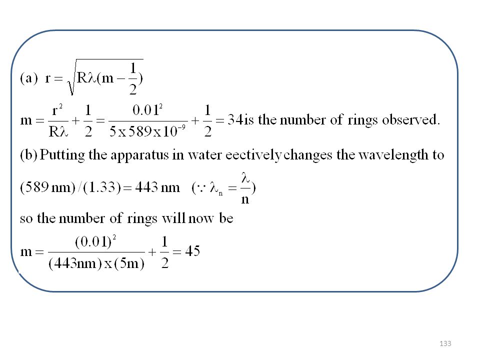
Problem 33: In Newton’s ring experiment, the radius of curvature R of the lens is 5m and its diameter is 20mm. How many rings are produced? How many rings would be seen if the arrangement is immersed in water (n=1.33)? (Assume that wavelength = 589nm) Given: λ = 589 nm Radius of curvature R= 5 m diameter of the ring=d=20mm Therefore, radius r= 10 mm=0.01 m (a) m=? (b) n=1.33, m=?
 (Assume that wavelength = 589nm) Given: λ = 589 nm. Radius of curvature R= 5 m. diameter of the ring=d=20mm. Therefore, radius r= 10 mm=0.01 m. (a) m= (b) n=1.33, m=")
134
Problem 34: The diameter of the tenth ring in a Newton’s rings apparatus changes from 1.42 to 1.27 cm as a liquid is introduced between the lens and the plate. Find the refraction of the liquid. Given: Radius of tenth bright ring in air: rair = 1.42 cm Radius of tenth bright ring in liquid: rliquid = 1.27 cm ring Refractive index of the liquid: nliquid = ?

136
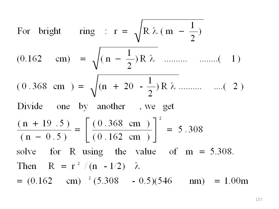
Problem 35: A Newton’s ring apparatus is used to determine the radius of curvature of a lens. The radii of the nth and (n+20)th bright rings are found to be 0.162cm and 0.368cm, respectively, in light of wavelength 546nm. Calculate the radius of curvature of the lower surface of the lens. Given: λ = 546 nm Radius of the nth ring=rn =0.162cm Radius of the (n+20)th =rn+20=0.368cm m=? Radius of curvature R= ?
th. =rn+20=0.368cm. m= Radius of curvature R=")
138
INTERFERENCE FROM THIN FILMS
OPTICAL PATH Distance traveled by light in a medium in the time interval of ‘t’ is d = vt Refractive index n = c/v Hence, ct = nd nd Optical path. d n MIT-MANIPAL BE-PHYSICS- INTERFERENCE

139
MICHELSON’S INTERFEROMETER
Purpose Interferometers are basic optical tools used to precisely measure wavelength, distance, index of refraction of optical beams. It is a device working on the principle of interference of light and is used in precise measurements of length or changes in length.

140
BE-PHYSICS- INTERFERENCE-2010-11
MICHELSON’S INTERFEROMETER Light from an extended monochromatic source P falls on a half-silvered mirror M. The incident beam is divided into reflected and transmitted beams of equal intensity (Division of amplitude). These two beams travel almost in perpendicular directions and will be reflected normally from movable mirror (M2) and fixed mirror (M1). B A G MIT-MANIPAL BE-PHYSICS- INTERFERENCE
. These two beams travel almost in perpendicular directions and will be reflected normally from movable mirror (M2) and fixed mirror (M1). B. A. G. MIT-MANIPAL. BE-PHYSICS- INTERFERENCE")
141
MICHELSON’S INTERFEROMETER
The two beams finally proceed towards a telescope (T) through which interference pattern of circular fringes will be seen. The interference occurs because the two light beams travel different paths between M and M1 or M2. Each beam travels its respective path twice. When the beams recombine, their path difference is 2 (d2 – d1). MIT-MANIPAL BE-PHYSICS- INTERFERENCE
 through which interference pattern of circular fringes will be seen. The interference occurs because the two light beams travel different paths between M and M1 or M2. Each beam travels its respective path twice. When the beams recombine, their path difference is 2 (d2 – d1). MIT-MANIPAL. BE-PHYSICS- INTERFERENCE")
142
MICHELSON’S INTERFEROMETER
The path difference can be changed by moving mirror M2. As M2 is moved, the circular fringes appear to grow or shrink depending on the direction of motion of M2. New rings appear at the center of the interference pattern and grow outward or larger rings collapse disappear at the center as they shrink. MIT-MANIPAL BE-PHYSICS- INTERFERENCE

143
MICHELSON’S INTERFEROMETER
Each fringe corresponds to a movement of the mirror M2 through one-half wavelength. The number of fringes is thus the same as the number of half wavelength. MIT-MANIPAL BE-PHYSICS- INTERFERENCE

144
If N fringes cross the field of view when mirror M2 is moved by d, then
d = N (/2) d is measured by a micrometer attached to M2. Thus microscopic length measurements can be made by this interferometer.
 d is measured by a micrometer attached to M2. Thus microscopic length measurements can be made by this interferometer.")
145
Michelson interferometer equation
The interferometer is used to measure changes in length by counting the number of interference fringes that pass the field of view as mirror M2 is moved. Length measurements made in this way can be accurate if large numbers of fringes are counted.

146
Applications Determination of wavelength
The fact that whenever the movable mirror moves by a fringe originates or vanishes at the center is used to determine from the equation 2d = N , where d is the distance moved and N, the number of fringes originated or vanished.

147
(nd–d)2= 2d(n-1) will be introduced.
Applications Determination of refractive index (n) When a thin film (whose refractive index n is to be determined) of thickness ‘d’ is introduced on the path of one of the interfering beams, an additional path difference (nd–d)2= 2d(n-1) will be introduced. As a result there will be shift of fringes. If ‘m’ fringes shift, then, 2d(n -1) = m from which ‘n’ can be determined. d
 When a thin film (whose refractive index n is to be determined) of thickness ‘d’ is introduced on the path of one of the interfering beams, an additional path difference. (nd–d)2= 2d(n-1) will be introduced. As a result there will be shift of fringes. If ‘m’ fringes shift, then, 2d(n -1) = m from which ‘n’ can be determined. d.")
148
MICHELSON’S INTERFEROMETER
Problem: SP 41-6 Yellow light (wavelength = 589nm) illuminates a Michelson interferometer. How many bright fringes will be counted as the mirror is moved through 1.0 cm? The number of fringes is the same as the number of half wavelengths in cm. Nλ= 2d N= 2 d/λ=2( x10-2 m)/(589 x 10-9m) = 33,956 fringes MIT-MANIPAL BE-PHYSICS- INTERFERENCE
 illuminates a Michelson interferometer. How many bright fringes will be counted as the mirror is moved through 1.0 cm The number of fringes is the same as the number of half wavelengths in cm. Nλ= 2d. N= 2 d/λ=2( x10-2 m)/(589 x 10-9m) = 33,956 fringes. MIT-MANIPAL. BE-PHYSICS- INTERFERENCE")
149
MICHELSON’S INTERFEROMETER
Problem: E41-39 If mirror M2 in Michelson’s interferometer is moved through 0.233mm, 792 fringes are counted with a light meter. What is the wavelength of the light used? Nλ= 2d λ= 2 d/N=2(0.233 mm)/792= 588 nm = 588 nm MIT-MANIPAL BE-PHYSICS- INTERFERENCE
/792= 588 nm. = 588 nm. MIT-MANIPAL. BE-PHYSICS- INTERFERENCE")
150
MICHELSON’S INTERFEROMETER
Problem: E41-40 An airtight chamber 5.0 cm long with glass windows is placed in one arm of a Michelson’s interferometer as indicated in Fig Light of wavelength λ = 500 nm is used. The air is slowly evacuated from the chamber using a vacuum pump. While the air is being removed, 60 fringes are observed to pass through the view. From these data find the index of refraction of air at atmospheric pressure. MIT-MANIPAL BE-PHYSICS- INTERFERENCE

151
Answer: The change in the optical path length is 2(nd – d) 2d(n-1)=mλ n=mλ/2d+1=
 2d(n-1)=mλ n=mλ/2d+1=")
152
Problem HRK-41-38: A thin film with n=1.42 for light of wavelength 589nm is placed in one arm of a Michelson interferometer. If a shift of 7 fringes occurs, what is the film thickness? Solution: 2d(n-1) = m d = mλ/ 2(n-1) d = 7 x (589 x10-9 m)/ 2(1.41-1) = 4.9 x 10⁻⁶ m
 = m d = mλ/ 2(n-1) d = 7 x (589 x10-9 m)/ 2(1.41-1) = 4.9 x 10⁻⁶ m.")
153
BE-PHYSICS- INTERFERENCE-2010-11
QUESTIONS – INTERFERENCE What is the necessary condition on the path length difference (and phase difference) between two waves that interfere (A) constructively and (B) destructively ? [2] Obtain an expression for the fringe-width in the case of interference of light of wavelength λ, from a double-slit of slit-separation d. [5] Explain the term coherence. [2] Obtain an expression for the intensity of light in double-slit interference using phasor-diagram. [5] MIT-MANIPAL BE-PHYSICS- INTERFERENCE
 between two waves that interfere (A) constructively and (B) destructively [2] Obtain an expression for the fringe-width in the case of interference of light of wavelength λ, from a double-slit of slit-separation d. [5] Explain the term coherence. [2] Obtain an expression for the intensity of light in double-slit interference using phasor-diagram. [5] MIT-MANIPAL. BE-PHYSICS- INTERFERENCE")
154
BE-PHYSICS- INTERFERENCE-2010-11
QUESTIONS – INTERFERENCE Draw a schematic plot of the intensity of light in a double-slit interference against phase-difference (and path-difference). [2] Explain the term reflection phase-shift. [1] Obtain the equations for thin-film interference. [2] Explain the interference-pattern in the case of wedge-shaped thin-films. [2] Obtain an expression for the radius of mTH order bright ring in the case of Newton’s rings. [5] Explain Michelson’s interferometer. Explain how microscopic length measurements are made in this. [4] MIT-MANIPAL BE-PHYSICS- INTERFERENCE
. [2] Explain the term reflection phase-shift. [1] Obtain the equations for thin-film interference. [2] Explain the interference-pattern in the case of wedge-shaped thin-films. [2] Obtain an expression for the radius of mTH order bright ring in the case of Newton’s rings. [5] Explain Michelson’s interferometer. Explain how microscopic length measurements are made in this. [4] MIT-MANIPAL. BE-PHYSICS- INTERFERENCE")
155
BE-PHYSICS- INTERFERENCE-2010-11
INTERFERENCE – ANSWERS TO PROBLEMS SP41-1: 0.12degree, 2.5mm E41-1: 0.22radian, 12 degrees E41-5: 650nm E41-9: 600nm SP41-2: E(t)= 3.83 Eo sin(t+22.5o ) E41-15: 0 degree E41-19: 1.21, 2.22, 8.13m SP41-3: 567nm (Yellow-green) SP41-4: 100nm E41-23: 552nm, 442nm E41-27: 840nm E41-29: 141 E41-33: 34, 45 SP41-6: fringes E41-39: 588nm MIT-MANIPAL BE-PHYSICS- INTERFERENCE
= 3.83 Eo sin(t+22.5o ) E41-15: 0 degree. E41-19: 1.21, 2.22, 8.13m. SP41-3: 567nm (Yellow-green) SP41-4: 100nm. E41-23: 552nm, 442nm. E41-27: 840nm. E41-29: 141. E41-33: 34, 45. SP41-6: fringes. E41-39: 588nm. MIT-MANIPAL. BE-PHYSICS- INTERFERENCE")
Similar presentations


>")


 sine waves are nice>")


 PHY 102: Waves & Quanta Topic 6 Interference John Cockburn (j.cockburn@... Room E15)>")

>")