Download presentation
Presentation is loading. Please wait.

1
AS Physics Unit 2 13 Optics Ks5 AS Physics 2450 Mr D Powell

2
Chapter Map

3
Trig Series Trigonometric functions can be expanded in power series, which facilitates approximations of the functions in extreme cases. The angle x must be in radians.

4
Small Angle Approximation...
One of the most important applications of trigonometric series is for situations involving very small angles. For such angles, the trigonometric functions can be approximated by the first term in their series. This gives the useful small angle approximations: Examples of the use of the small angle approximation are in the calculation of the period of a simple pendulum, and the calculation of the intensity minima in single slit diffraction. This approximation is used in most of the common expressions of geometrical optics which are built on the concept of surface power for lenses. This approximation sin x = x reaches a 1% error at about 14 degrees

5
Maths puzzling.... Degrees Theta Rad Sin Theta Difference 0.00 1 0.02 2 0.03 3 0.05 4 0.07 5 0.09 6 0.10 7 0.12 8 0.14 9 0.16 10 0.17 20 0.35 0.34 -0.01 30 0.52 0.50 -0.02 40 0.70 0.64 -0.06 50 0.87 0.77 -0.11 60 1.05 -0.18 70 1.22 0.94 -0.28 80 1.40 0.98 -0.41 Construct an excel spreadsheet to explore and prove the concept that for the situation where <10 and measured in radians;

6
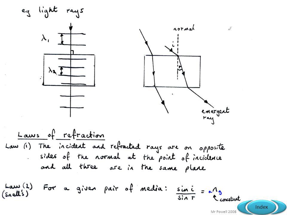
13.1 Refraction of light Specification link-up 3.2.3: Refraction at a plane Surface What do we mean by ‘rays’? What is Snell’s law? Does refraction differ for a light ray travelling from a transparent substance into air?

7
Refraction of Light

8
Refraction of Light This happens when the direction of travel of a wave changes as it travels from one medium to another. This is due to a change in wave speed.

10
Snells Law Θ1 = angle of incidence Θ2 = angle of refraction
Incident ray normal 1 Refracted ray 2 1. The incident ray, the refracted ray and the normal all lie in the same plane. 2. For two given media, the ratio of the sine of the angle of incidence to the sine of the angle of refraction is constant.

11
Verification of Snells Law
Why not try it out for a glass prism? Look at the example results first… i r sin i sin r n 10 6.6 0.174 0.115 1.5 20 13.2 0.342 0.228 30 19.5 0.5 0.334 40 25.4 0.643 0.429 50 30.7 0.766 0.511 60 35.3 0.866 0.578 70 38.8 0.94 0.627

12
Arsenic trisulfide and sulfur in methylene iodide 1.9
Material λ (nm) n Vacuum 1 (per definition) STP 0 °C and 1 atm Air 589.29 Carbon dioxide 20 °C Water 1.3330 Arsenic trisulfide and sulfur in methylene iodide 1.9 room temperature Diamond 2.419 Strontium titanate 2.41 Amber 1.55 Water ice 1.31 cornea (human) 1.3375
 n. Vacuum. 1 (per definition) STP °C and 1 atm. Air Carbon dioxide °C. Water Arsenic trisulfide and sulfur in methylene iodide room temperature. Diamond Strontium titanate Amber Water ice cornea (human)")
13
Equilateral Prisms Sometimes it is better to think of Snells law as...
Where you have two mediums. It does not matter which way they are around or what they are as long as you plug in the refractive mediums number. The equation simplifies to n = 1 for air. For an equilateral prism you can use this construct to work out the refraction as unlike a rectangular prism i1 i2 In essence what we mean is that every angle of reflection & refraction is different for the double refraction in an equilateral prism. You have to draw it out to work it out. Q4 page 189. Hint: Draw a scale diagram 5cm each side. 60 angles. First refracted angle 22 Measure 2nd incident 38 Calc 2nd refracted 72.6

14
Equilateral Prisms The complex version….

15
Homework - Fishes & Straws
Diving birds automatically adjust for refraction effects when hunting fish. This straw shows it clearly. Try it out with a pencil and glass at home then try and explain it with a ray diagram and text…

16
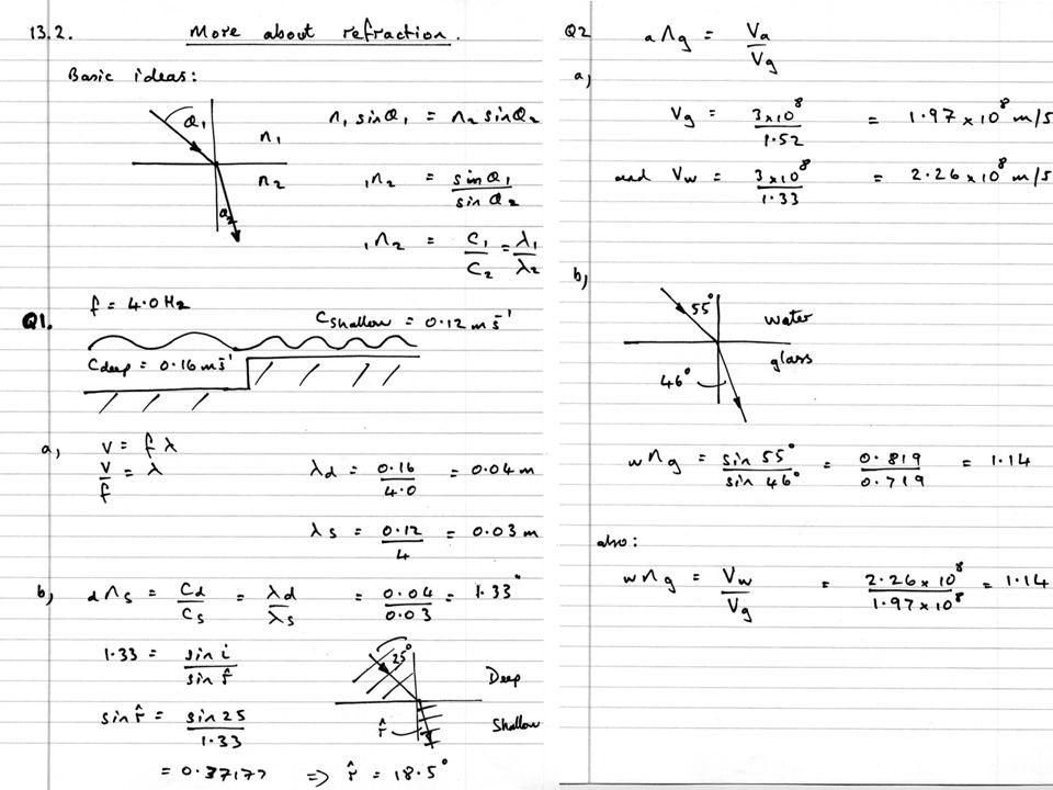
13.2 More about refraction Specification link-up 3.2.3: Refraction at a plane Surface What happens to the speed of light waves when they enter a material such as water? How is refractive index related to the speed of light waves? Why does a glass prism split sunlight into the colours of a spectrum?

17
What happens? air glass / water

18
REFRACTIVE INDEX FROM 1 TO 2
Explaining it... REFRACTIVE INDEX FROM 1 TO 2 Optically less dense medium (1) Optically denser medium (2) Waves travel SLOWER Wavelength REDUCED Frequency UNCHANGED NB: If c = f if speed is less as light finds it harder to get through glass the must go down as well
 Optically denser medium (2) Waves travel SLOWER. Wavelength REDUCED. Frequency UNCHANGED. NB: If c = f if speed is less as light finds it harder to get through glass the must go down as well.")
19
Problem drawn out... If we try and think about the problem by drawing out the wave front and looking at triangles.. Then considering the constant velocity of the wave which then changes to a new constant velocity.

20
r Triangles again... ct=YY’ i XY’ XY’ cst=XX’
Think about how the wave slows when it reaches the medium. We can express the distance it travels YY’ or XX’ simply by s/v=t (constant vel) Then similar triangles result in a sin function for the angle calculations and an expression for a ratio of velocities. Finally we can express this ratio as what we call a refractive index or “how much the light slows down”. Higher is slower!
 Then similar triangles result in a sin function for the angle calculations and an expression for a ratio of velocities. Finally we can express this ratio as what we call a refractive index or how much the light slows down . Higher is slower!")
21
Speed of Light... The speed of light, usually denoted by c, is a physical constant, so named because it is the speed at which light and all other electromagnetic radiation travels in vacuum. Its value is exactly 299,792,458 ms-1 The speed at which light propagates through transparent materials, such as glass or air, is less than c. The ratio between c and the speed v at which light travels in a material is called the refractive index n of the material (n = c / v). For example, for visible light the refractive index of glass is typically around 1.5, meaning that light in glass travels at c / 1.5 ≈ 200,000 km/s; the refractive index of air for visible light is about , so the speed of light in air is very close to c. Wavelength REDUCED Waves travel SLOWER Frequency UNCHANGED
. For example, for visible light the refractive index of glass is typically around 1.5, meaning that light in glass travels at c / 1.5 ≈ 200,000 km/s; the refractive index of air for visible light is about , so the speed of light in air is very close to c. Wavelength REDUCED. Waves travel SLOWER. Frequency UNCHANGED.")
26
13.3 Total Internal Reflection
Specification link-up 3.2.3: Refraction at a plane surface What are the conditions for total internal reflection? How is the critical angle related to refractive index? Why do diamonds sparkle?

27
TIR As the angle of incidence increases towards the critical
weak reflected ray As the angle of incidence increases towards the critical angle ( glass = 420 ) the refracted ray gets weaker and the reflected ray gets stronger. NB: When light travels from an optically denser medium to a less dense medium, rays are bent away from the normal. The incident substance has a larger refractive index than the other substance
 the. refracted ray gets weaker. and the reflected ray gets. stronger. NB: When light travels from an optically denser medium to a less dense medium, rays are bent away from the normal. The incident substance has a larger refractive index than the other substance.")
28
Critical angle depends upon the refractive indices of the media
1 2 C HENCE If medium 2 is air, n2 = 1, and so

29
Critical Angle Example?
For Water 1 2 C AIR WATER C = 48.80 C = 41.80 For Crown Glass

30
Diamonds Sparkle the most!
Diamond has a refractive index of This means that colours are spread out more. TIR occurs many times inside the diamond before emerging. Can you work out the critical angle? 24.44

31
Applications of Fibre Optics…
End probe containing coherent bundle, incoherent bundle, lens and surgical instruments Controls Eyepiece Light injected here ENDOSCOPE This is an endoscope image of the inside of the throat. The arrows point to the vocal chords

32
Applications of Fibre Optics…
The endoscope is inserted into a body cavity, which is then illuminated through an in coherent bundle of fibres A lens over the end of the other bundle is used to form an image of the body

33
Applications of Fibre Optics…
A coherent bundle means that the fibre ends at each end must be in the same relative positions

34
Applications of Fibre Optics…
A COHERENT BUNDLE: A bundle of optical fibres in which the relative spatial coordinates of each fibres are the same at the two ends of the bundle. Such a bundle are used for the transmission of images. A NON-COHERENT FIBRE bundle, as you would expect, does not have this precise matrix alignment since they need only transmit light for illumination purposes. They are cheaper to produce.

35
Applications of Fibre Optics…
PROBLEM: Input light rays cannot be precisely parallel. core cladding Rays taking different paths will take different times to travel along the fibre, resulting in the jumbling of the signal. Solution : Monomode fibre only 5μm in diameter

36
Applications of Fibre Optics…
Optical fibres in communications Purpose?

37
Applications of Fibre Optics…

38
Applications of Fibre Optics…

39
Pulse broadening with spectral dispersion
Pulse out with spectral dispersion Pulse in - white light

40
TIR uses…. 1) Endoscopes (a medical device used to see inside the body): 2) Binoculars and periscopes (using “reflecting prisms”)
 Endoscopes (a medical device used to see inside the body): 2) Binoculars and periscopes (using reflecting prisms ) .")
41
Mirage….. Hot Desert Sand air layers Water for my hump! Air layers closer to the sand are hotter and less dense. Light from the sky is successively bent until a critical angle is reached and then total internal reflection occurs. A mirage "water" illusion is seen because the mind initially interprets the light rays reaching our eyes as having come along a straight path originating from the ground. Thus, the image of that patch of sky we see "on the ground" is interpreted as a surface "pool of water."

42
Endoscopes – coherence
Fibre Summary.... Features/ Issues Core Cladding Endoscopes – coherence Spectral Dispersion Multipath Dispersion Critical Angle (TIR) Mono-mode
 Mono-mode.")
44
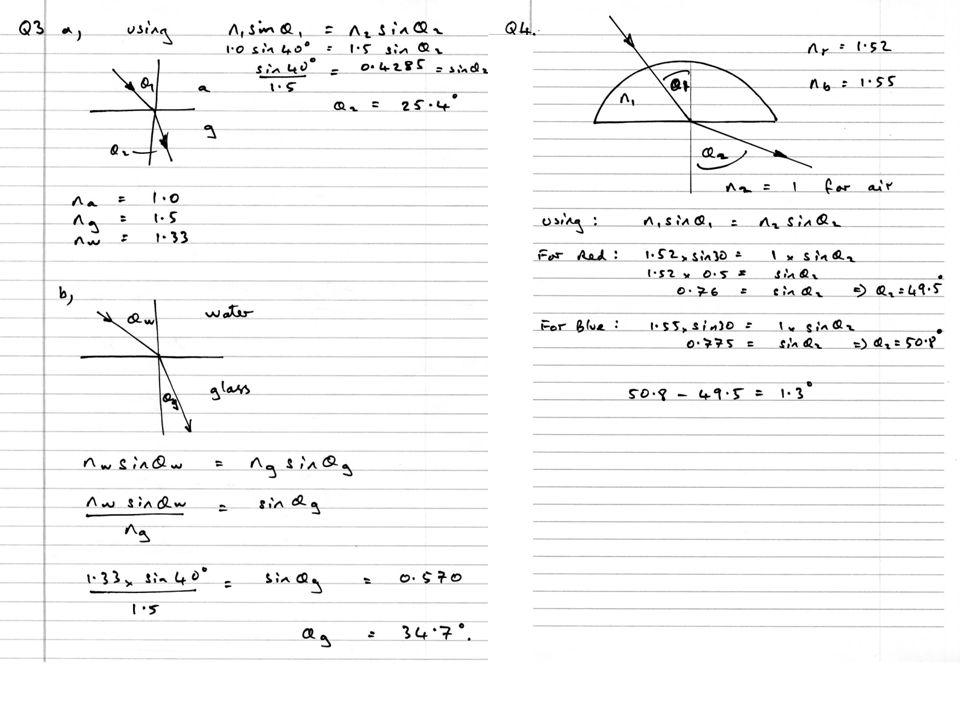
Q3b

47
13.4 Double Slit Interference
Specification link-up 3.2.3: Interference What is the general condition for the formation of a bright fringe? Are Young’s fringes equally spaced? What factors could be (i) increased, or (ii) decreased, to increase the fringe spacing?
 increased, or (ii) decreased, to increase the fringe spacing v=AMBcgVlamoU&feature=related.")
48
Interference Rules…. For an interference pattern to be observable….
The waves must be of the same type and must meet at a point. The waves are coherent, i.e. the waves from each source maintain a constant phase difference. The waves must have the same wavelength and roughly the same amplitude. The waves must be both either unpolarised or have the same plane of polarisation. NB: Two sources are said to be coherent if waves from the sources have a constant phase difference between them.

49
Young's Double Slit Interference - Introduction
In 1801, an English physicist named Thomas Young performed an experiment that strongly inferred the wave-like nature of light. Because he believed that light was composed of waves, Young reasoned that some type of interaction would occur when two light waves met. Young passed sunlight through a red colour filter then single slit in a screen to produce coherent light. Then another screen that has a double slit. The results of interference between the diffracted light beams can be visualised as light intensity distributions on the dark film. His hypothesis was that if light were wave-like in nature, then it should behave in a manner similar to ripples or waves on a pond of water. They should either cancel or add at different points depending on the distance from the slit.

50
3D View….

51
Wavefront View… Single source passes through single then double slits (a few apart). The waves diffract then interference occurs where the beams cross. 1st bright fringe central fringe 1st bright fringe
. The waves diffract then interference occurs where the beams cross. 1st bright. fringe. central. fringe. 1st bright. fringe.")
52
Results…. Here are some possible ideas of what could happen….

53
Young's Double Slit Interference - Results
Young observed that when the slits were large, spaced far apart and close to the screen, then two overlapping patches of light formed on the screen. However, when he reduced the size of the slits and brought them closer together, the light passing through the slits and onto the screen produced distinct bands of colour separated by dark regions. Young coined the term interference fringes to describe the bands and realised that these coloured bands could only be produced if light were acting like a wave. Pattern is wider as slit gets smaller…

54
Young's Double Slits Young actually worked out a formula for the theory of how far the fringes are separated (w). It related the distance from S1 or S2 to screen (D) the wavelength of the light () and s (slit spacing – distance between centres of slits S1 or S2) W
. It related the distance from S1 or S2 to screen (D) the wavelength of the light () and s (slit spacing – distance between centres of slits S1 or S2) W.")
55
Factors affecting fringe separation
Another way to express this idea is that Fringe separation…. Which is the same thing! Δx is increased if distance to the screen D is increased. Δx is decreased if slit separation a is increased. Δx is increased as wavelength of light λ is increased

56
Another Example….

57
Another Example….

58
Test yourself…. Use the example data to test out the theory. Try several versions where you can see a change in… Slit separation Distance Wavelength s = wavelength = 590nm D = slit to screen distance = 1m S = slit separation = 0.4 mm W = fringe width = 1.48mm W

59
Complex Theory Consider the diagram above where at P the fringe is observed. Light emitted from S1 arrives later than S2 as it travels further. The difference in the travel is called the path difference. We find that for a wave to add constructively the path difference must be a whole wavelength i.e. m = 1 when S1P-S2P = m Hence: light emitted at same time from S1, S2 will arrive in phase at P if reinforcement occurs We find that for a wave to cancel the path difference must be a ½ wavelength i.e. m = 1 when S1P-S2P = (m+0.5) Hence: light emitted at same time from S1, S2 will arrive out of phase at P if cancellation occurs.
 Hence: light emitted at same time from S1, S2 will arrive out of phase at P if cancellation occurs.")
60
Path difference Phase difference

61
For constructive interference at the screen:
( ie a bright fringe ) Wave fronts from S1 and S2 must arrive at the screen in phase with a path difference of a whole number of wavelengths For destructive interference at the screen: ( ie a dark fringe ) Wave fronts from S1 and S2 must arrive out of phase with a path difference of half a wavelength
 Wave fronts from S1 and S2 must arrive at the screen in phase. with a path difference of a whole number of wavelengths. For destructive interference at the screen: ( ie a dark fringe ) Wave fronts from S1 and S2 must arrive out of phase. with a path difference of half a wavelength.")
62
Complex Theory Point P has been selected so that QP = S2P
This means that path difference is S1P – S2P or S1P – S2P = S1Q Consider the triangles S1S2Q and MOP. M is midpoint between slits and O the midpoint of brightest fringe The two triangles are similar in terms of angles PMO and QS2S1 We also know that sin = tan when <5 So we can say that for triangle OMP and S1S2Q that they equal the same ratios (see eqs) This works for each fringe where P is the m’th bright fringe (m = 0, 1,2,3) w is fringe separation, s spacing, D distance to screen perpendicular. For this to be true s << D.
 This works for each fringe where P is the m’th bright fringe (m = 0, 1,2,3) w is fringe separation, s spacing, D distance to screen perpendicular. For this to be true s << D.")
63
13.5 More about Interference
Specification link-up 3.2.3: Interference What are coherent sources? Why are slits used, rather than two separate light sources, in Young’s experiment? What are the roles of diffraction, and interference, when producing Young’s fringes?

64
What a great use for a LASER
Obi Wan or Obi Non! What a great use for a LASER Great idea for cutting metals, fighting and generally chopping up any undesirables! However, what the Jedi Knights did not reckon on is E = hf. TASK Can you describe using a Quantum Physics explanation why this is a load of “Hoki Magic” and what would happen if light could behave this way?

65
What does this show?

66
Rhodamine 6G dye (tunable)
Wavelength examples... A ruby laser is a solid-state laser and emits at a wavelength of 694 nm. Other lasing mediums can be selected based on the desired emission wavelength (see table below), power needed, and pulse duration. Some lasers are very powerful, such as the CO2 laser, which can cut through steel. The reason that the CO2 laser is so dangerous is because it emits laser light in the infrared and microwave region of the spectrum. Infrared radiation is heat, and this laser basically melts through whatever it is focused upon. Other lasers, such as diode lasers, are very weak and are used in today’s pocket laser pointers. These lasers typically emit a red beam of light that has a wavelength between 630 nm and 680 nm. Lasers are utilised in industry and research to do many things, including using intense laser light to excite other molecules to observe what happens to them. Laser Type Wavelength (nm) Argon fluoride (UV) 193 Krypton fluoride (UV) 248 Xenon chloride (UV) 308 Nitrogen (UV) 337 Argon (blue) 488 Argon (green) 514 Helium neon (green) 543 Helium neon (red) 633 Rhodamine 6G dye (tunable) Ruby (CrAlO3) (red) 694 Nd:Yag (NIR) 1064 Carbon dioxide (FIR) 10600
, power needed, and pulse duration. Some lasers are very powerful, such as the CO2 laser, which can cut through steel. The reason that the CO2 laser is so dangerous is because it emits laser light in the infrared and microwave region of the spectrum. Infrared radiation is heat, and this laser basically melts through whatever it is focused upon. Other lasers, such as diode lasers, are very weak and are used in today’s pocket laser pointers. These lasers typically emit a red beam of light that has a wavelength between 630 nm and 680 nm. Lasers are utilised in industry and research to do many things, including using intense laser light to excite other molecules to observe what happens to them. Laser Type. Wavelength (nm) Argon fluoride (UV) 193. Krypton fluoride (UV) 248. Xenon chloride (UV) 308. Nitrogen (UV) 337. Argon (blue) 488. Argon (green) 514. Helium neon (green) 543. Helium neon (red) 633. Rhodamine 6G dye (tunable) Ruby (CrAlO3) (red) 694. Nd:Yag (NIR) Carbon dioxide (FIR)")
67
Summary E = hf P = nhf n = number of photons arriving per second

68
Applications of Lasers

69
Applications of Lasers II - Coms

70
13.6 Diffraction Specification link-up 3.2.3: Diffraction
Why is diffraction of light important in the design of optical instruments? How does the single slit diffraction pattern compare with the pattern of Young’s fringes? What is the effect of the single slit pattern on the brightness of Young’s fringes?

71
Laser Light The most common and inexpensive gas laser, the helium-neon laser is usually constructed to operate in the red at nm. One of the excited levels of helium at eV is very close to a level in neon at eV, so close in fact that upon collision of a helium and a neon atom, the energy can be transferred from the helium to the neon atom. Helium-neon lasers can still be dangerous! An unfocused HeNe laser is dangerous to stare at directly and will blind you. You must be careful to avoid refracted beams whilst conducting experiments.

72
Double Slit Interference

73
Double Single

74
Single Slit This is an attempt to more clearly visualise the nature of single slit diffraction. The phenomenon of diffraction involves the spreading out of waves past openings which are on the order of the wavelength of the wave.

75
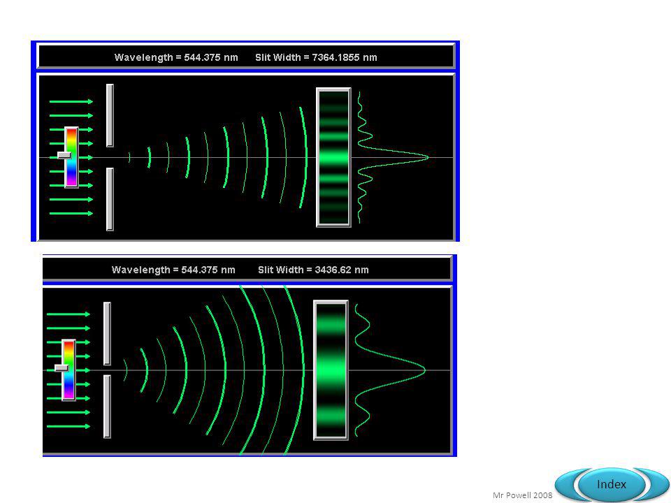
Slit Width One of the characteristics of single slit diffraction is that a narrower slit will give a wider diffraction pattern as illustrated in the images.

76
Or can view as a water wave (single slit diffraction)
Semi circular wave fronts First minima & maxima become visible Diffraction is the spreading of wavefronts around corners and obstacles. If the slit gets narrower diffraction increases. If the wavelength increases diffraction increases.

77
Single Slit Diffraction
The diffraction pattern here is taken with a helium-neon laser and a narrow single slit. We can see…. This means that if you project a light source i.e. laser, measure the width of the central blob you can work out the wavelength of the light. The formulae you need for the exam is called fringe spacing…

78
Single Slit Diffraction
The diffraction pattern here is taken with a helium-neon laser and a narrow single slit. We can see…. This means that if you project a light source i.e. laser, measure the width of the central blob you can work out the wavelength of the light. The formulae you need for the exam is called fringe spacing… But remember that the central fringe is twice this! a = w in this case

79
Single Slit Diffraction...

80
It can be shown that the first minima occurs when sin Ə = λ/a .
Central maxima Q1 Find the angle at which the first minima occurs using microwaves of wavelength 3 cm when directed towards a gap of: 1) 6cm 2) 4cm Q2 Find the angle at which the first minima occurs using lightwaves of wavelength 500 nm when directed towards a pupil of diameter: 1) 6mm 2) 4mm
 6cm. 2) 4cm. Q2 Find the angle at which the first minima occurs using lightwaves. of wavelength 500 nm when directed towards a pupil of diameter: 1) 6mm. 2) 4mm.")
81
* central fringe is twice as wide as the other fringes
Visit : Blue light has narrower fringes So cameras and microscopes can see more detail using blue filters Points to note: * central fringe is twice as wide as the other fringes * intensity decreases from the centre * Central Fringe width W = λ/a x 2D

84
Experimental observations from the double slit
i) For a pair of slits 0.5 mm apart: λ red » λ blue ii) Using white light, fringes appear from all the various wavelengths present and do not overlap exactly, hence coloured fringes * Inner fringes are tinged with blue on the inside and red on the outside Diffraction is the spreading of wavefronts around corners and obstacles. If the slit gets narrower diffraction increases. If the wavelength increases diffraction increases.
 For a pair of slits 0.5 mm apart: λ red » λ blue. ii) Using white light, fringes appear from all the various wavelengths present. and do not overlap exactly, hence coloured fringes. * Inner fringes are tinged with blue on the inside. and red on the outside. Diffraction is the spreading of wavefronts around corners and obstacles. If the slit gets narrower diffraction increases. If the wavelength increases diffraction increases.")
85
Experimental observations from the double slit cont’d
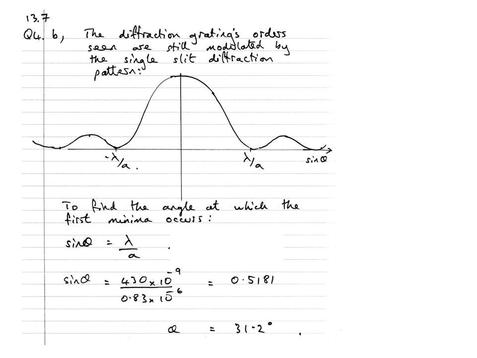
iii) Fringes obtained using slits 0.5 mm apart drawn with different widths The double slit interference pattern is modulated by the single slit pattern (a) (b) (b) thick slits Missing fringes (a) thin slits Diffraction is the spreading of wavefronts around corners and obstacles. If the slit gets narrower diffraction increases. If the wavelength increases diffraction increases.
 Fringes obtained using slits 0.5 mm apart drawn with different widths. The double slit interference. pattern is modulated. by the single slit pattern. (a) (b) (b) thick slits. Missing fringes. (a) thin slits. Diffraction is the spreading of wavefronts around corners and obstacles. If the slit gets narrower diffraction increases. If the wavelength increases diffraction increases.")
86
Double & Single Slit Interference
Same double-slit assembly (0.7mm between slits); in top image, one slit is closed. Note that the single-slit diffraction pattern — the faint spots on either side of the main band — is also seen in the double-slit image, but at twice the intensity and with the addition of many smaller interference fringes.
; in top image, one slit is closed. Note that the single-slit diffraction pattern — the faint spots on either side of the main band — is also seen in the double-slit image, but at twice the intensity and with the addition of many smaller interference fringes.")
87
NB: The double slit fringes are still in the same place
Summary of Patterns The double slit pattern is superimposed on the much broader single slit diffraction pattern. The bright central maximum is crossed by the double slit interference pattern, but the intensity still falls to zero where minima are predicted from single slit diffraction. The brightness of each bright fringe due to the double slit pattern will be “modulated” by the intensity envelope of the single slit pattern. NB: The double slit fringes are still in the same place Single slit pattern Double slit pattern

88
Single Slit and Double Slit?
A diffraction pattern formed by a real double slit. The width of each slit is much bigger than the wavelength of the light. This is a real photo. This idealised pattern is not likely to occur in real life. To get it, you would need each slit to be comparable in size to the wavelength of the light, but that's not usually possible. This is not a real photo. A real photo of a single-slit diffraction pattern caused by a slit whose width is the same as the widths of the slits used to make the top pattern.

95
13.7 The Diffraction Grating
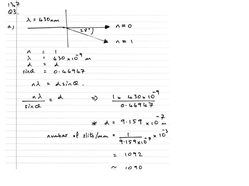
Specification link-up 3.2.3: Diffraction Why does a diffraction grating diffract monochromatic light in certain directions only? If a coarser grating is used, what is the effect on the number of diffracted beams produced and on the speed of each diffracted beam? How can we determine the grating spacing for any given grating, if it is not known? Derive the Generic Diffraction Formulae

96
Laser Diffraction! Model = 1 x 10⁻⁶m 1.6 microns ,dvd is .74 microns Experiemental 5.4 microns Can you work out the spacing of lines on a CD if light is nanometres. (0.5 to 0.9mW Power) L = 229.5cm Opp = 55.5cm 57.1cm 58.3cm (three repeats 2nd order)
 L = 229.5cm. Opp = 55.5cm. 57.1cm. 58.3cm. (three repeats 2nd order)")
97
Light through a diffraction grating...
If we pass light rays through a diffraction grating. Which is made up of very small slits in a regular pattern we find that there is a pattern of dots formed on a screen. This is because the wave fronts interfere with each other destructively and constructively. Simply put a wave front which emerges at point P is reinforced by another wave front acting in phase at point Q and then R. The result is a wave front along Y &Z

98
Light through a diffraction grating...
If we consider the triangle as shown in the zoomed in diagram we can see that an angle can be worked out from knowing QP and QY and then similar triangles rule used to find out the angle of the rays as they appear on a screen. We can use the idea of constructive interference and take the idea that from trigonometry & But we also know that the length QY should be the length of a whole wavelength and also that QP is the slit spacing.

99
Light through a diffraction grating...
We can also now think about the idea that this happens not only once but several times or orders. Each time we have a whole wavelength we get the construction of a new wave front or “n” wave front. Our formulae can be changed to; d = slit spacing = angle from normal n = order of diffraction = wavelength of the light

100
Practical Setup a laser light source and use the formula below to check the wavelength of the light. Your quoted value is 632.8nm(632.8 x 10⁻⁹m). Your teacher will give you a slit which has 300 lines per mm or a spacing d = 3.33 x 10⁻⁶m. Use this one at first to check the calculation. Then try and take some other readings. d = slit spacing = angle from normal n = order of diffraction = wavelength of the light

101
Distance Diffracted (m)
Results..... n Distance (m) Distance Diffracted (m) Hyp opp /hyp = sin(theta) d Lambda (m) lambda (nm) d/lambda (max orders) 1 0.5 0.099 E-06 E-07 647 5 2 0.208 E-07 640 3 0.348 6.3473E-07 635 Ave 641 Quoted! 632.8 Within... 98.7 1.30%
 Distance Diffracted (m) Hyp. opp /hyp = sin(theta) d. Lambda (m) lambda (nm) d/lambda (max orders) E E E E Ave Quoted! Within %")
102
Use of Emission Spectrums?
How do we know which elements stars are made up from? How do we know the age of stars? Scientists can begin to answer these questions once they have an understanding of line spectra.

103
What are we talking about?
When we talk about “Line Spectra” for an atom we simply mean that an atom can absorb or emit radiation at certain frequencies. If we look at the frequencies emitted or absorbed we can see a spectrum with omissions. 656nm

104
There are three types that you might see....
How are they made? There are three types that you might see....

105
Other Elements Emission Spectra....

106
M Spectral Gases Image we look towards a star and then pass its light through a cold gas then then a prism to make an absorption spectrum what elements would be present? Star X

107
M Spectral Gases & Shift
Here are three spectral diagrams from a star. The first one is a reference diagram. The second two are shifted across to the red end of the spectrum. Hence, they are moving away from us. We can tell how fast they are moving by the shift. The middle band is actually shifted by a distance of 100Å (angstrom) or 100 x m. (10nm). This translates to a speed of 24,000 km/hour or 15,000 mph. The bottom band is shifted by 760Å or (76nm) which translates to a speed of 136,000km/hour or 84,000 mph.
 or 100 x m. (10nm). This translates to a speed of 24,000 km/hour or 15,000 mph. The bottom band is shifted by 760Å or (76nm) which translates to a speed of 136,000km/hour or 84,000 mph.")
108
Spectral Gases Conclusion
M Spectral Gases Conclusion So these pictures show us that the lower stars are moving away from us Also the further they are away the faster they travel.

Similar presentations


 Special Sequences & Series>")


>")

 Review for the Final.>")
Sin x = -1/2 2)Tan x = 1.>")


 Learning Objective: To compute values of common trig expressions, both by hand.>")


